
Frame grabbing with laser scanner with sweeping by silicon planar electrostatics actuator

a laser scanner and actuator technology, applied in the direction of electrostatic generators/motors, electrostatic motors, instruments, etc., can solve the problems of inability to capture video frames, laser scanners with increased depth of field, and poor depth of field, etc., to achieve low cost, high speed, and small size

Inactive Publication Date: 2005-04-12
INTERMEC IP
View PDF1 Cites 27 Cited by
  • Summary
  • Abstract
  • Description
  • Claims
  • Application Information

AI Technical Summary

Benefits of technology

Previous video frame capture was performed optically, for example, in a case of 2D CCD video image. Optical solutions suffer from poor depth of field. Contrarily, laser scanners have increased depth of field, but are incapable of video frame capture. To perform video frame capture with a laser it is necessary to record or device the time sequenced laser beam location. Previously, the laser beam location has been detected via the use of secondary circuits which monitor the reflected beam in a CCD matrix and / or window reflected light 2D CCD schemes. These solutions require additional components dedicated specifically to determining beam location. The present invention provides a solution that does not require additional components, thereby creating materials, manufacturing and energy consumption efficiencies.
Laser scanners make it possible to obtain images of great depth, i.e. they can read images from far away, of field by the dissociation of the means of collection of light and spot production. Indeed, the spatial resolution of a laser scanner is related primarily to the size of the spot. The spot can be reduced to the limit of diffraction.
The last decade saw an emerging technology, Micro Electro Mechanical Systems (MEMS), which makes it possible to produce low cost deflectors with several degrees of freedom in a very small size, while oscillating at high speed and consuming little power. One can thus imagine a pen type 2D symbol reader with high depth of field, projecting a laser scanning of rectangular form delimiting precisely and with brightness the reading zone. It would be possible to change dynamically the sweep angles (zoom effect), making it possible to reduce the number of samples necessary.
Laser scanners lend themselves well to 3D frame grabbing by modulating the beam amplitude and by detecting the margin of dephasing of the reflected signal, making it possible to produce endoscope 3D.
The principal problem arising for acquiring a specially ordered image is the stability of the positioning function of the spot in the scene. There are several electro-mechanical technologies useful for stabilizing the positioning function. One can classify them into two families. The first family includes devices with high inertia and the second, those with low inertia. The high inertia devices use one or more rotating polygons which, by their accumulated kinetic energy, make it possible to make the angular velocity of the spot constant and insensitive to external disturbances. One can thus reach high speeds by the multiplication of the number of facets of the polygons and the use of synchronous motors or turbines with air cushion. These high inertia systems are cumbersome because of their mass and high energy consumption. Technologies with low inertia include oscillating systems actuated by electrostatic, piezoelectric, or magnetic forces. The weak inertia of these devices makes it possible to maintain them in resonance with little energy. One of their major defects until now were their relatively low (less than for 1000 Hz, angles of oscillation 40°) angular velocities.
A micro actuator MEMS consists of an oscillating assembly made out of a chip of silicon of a few tens of microns thickness and surface area approximately equal to that the spot. The absence of wearing parts (the bearings are replaced by two arms of silicon), and the reduction of the moment of inertia allow high frequencies of oscillation with little input energy. Moreover, the miniaturization of the deflector allows the packaging in a rarefied atmosphere which reduces damping due to air resistance and increases the amplitude of oscillation (less than 30 kHz, for angles of oscillation of 40°).

Problems solved by technology

Optical solutions suffer from poor depth of field.
Contrarily, laser scanners have increased depth of field, but are incapable of video frame capture.
It is more difficult to acquire an image with a sweeping device because guaranteeing with precision the position of the spot in the scene requires cumbersome and expensive hardware.
Therefore the sweeping devices have been limited to applications of high added value such as display and 3D acquisition, or for the capture of one-dimensional images such as 1 D bar codes and stacked bar codes.

Method used


Image

  • Frame grabbing with laser scanner with sweeping by silicon planar electrostatics actuator
  • Frame grabbing with laser scanner with sweeping by silicon planar electrostatics actuator
  • Frame grabbing with laser scanner with sweeping by silicon planar electrostatics actuator

Examples


Embodiment Construction

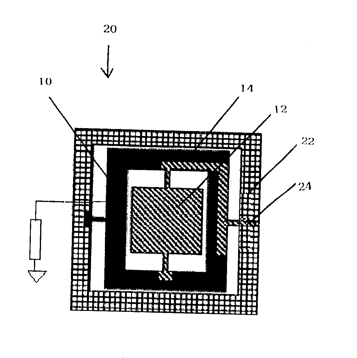
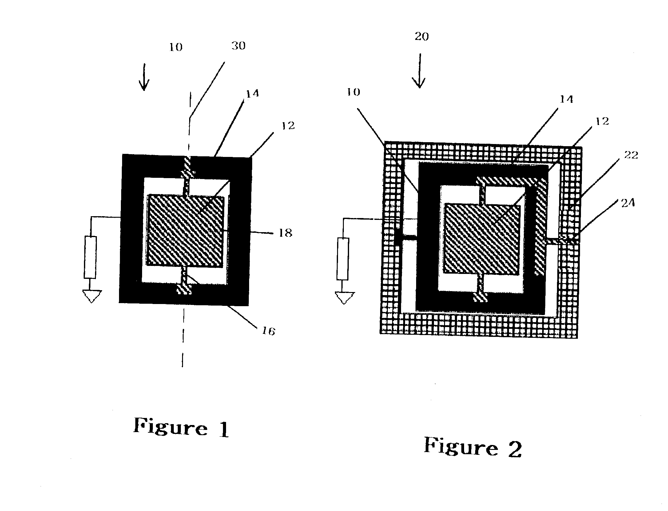
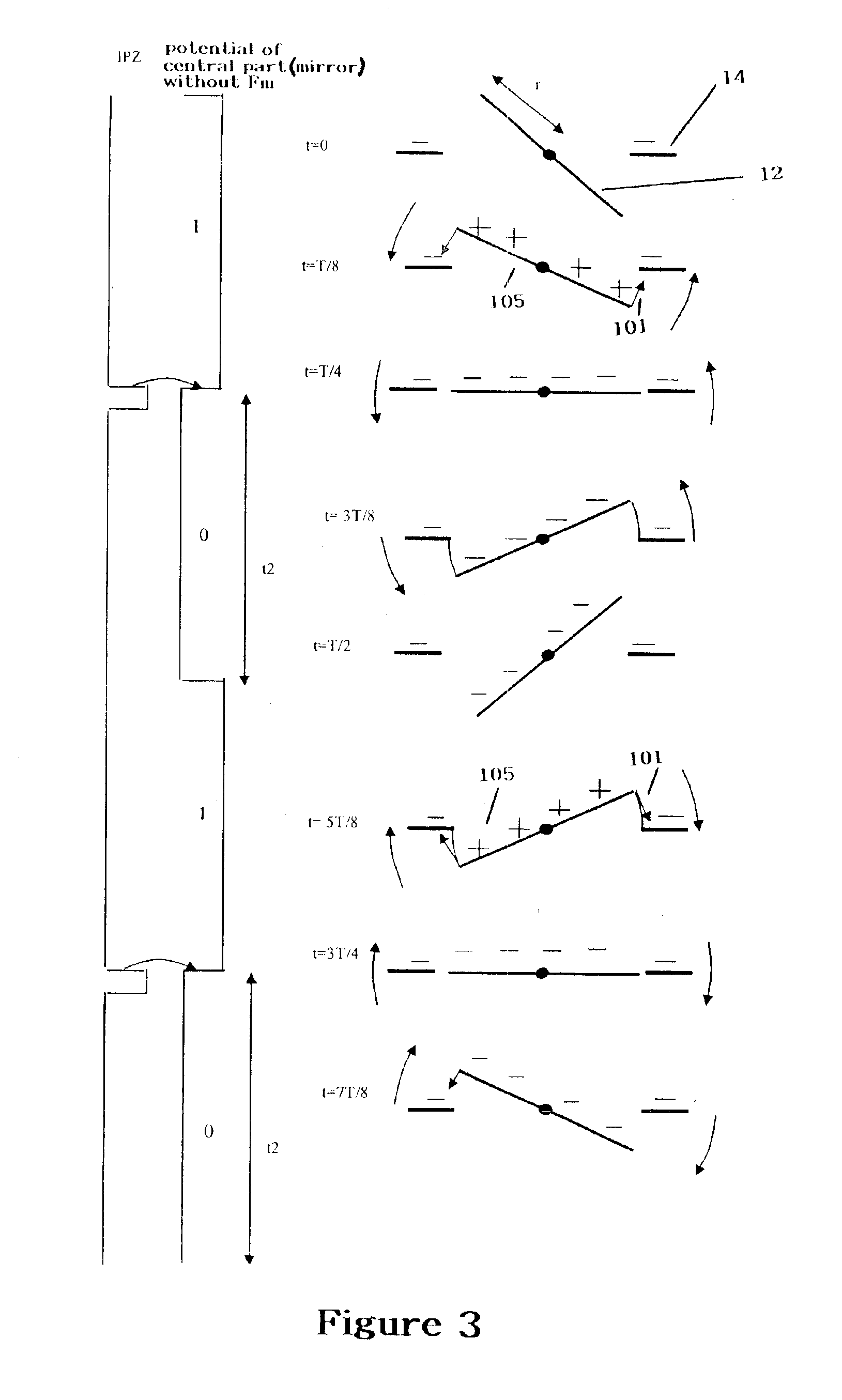
The 2D micro actuator of the present invention is based on the technology of the micro planar resonant actuator developed in partnership with Fraunhofer Institute of Dresden within the framework of the project Europeen Mirage. A micro actuator 10 includes a mirror 12 suspended within a framework 14 by two torsion arms 16 defining an axis of oscillation 30. The 2D micro actuator 20 of the present invention includes a 1D micro actuator 10 suspended within a second framework 22 by two torsion bars 24 and two pairs of orthogonal additional electrodes. The 2D micro actuator 20 thus obtained is a monolithic part of silicon which can be manufactured according to standard processes used for semi conductors CMOS. Several thousands of micro actuators can be carried out in parallel on same the wafer. The geometry out of comb of the electrodes allows one to obtain angles of oscillation up to 40μ with less than 20 V, for a frequency of oscillation of 140 hertz to 20 kHz. The frame 14 of the micr...


PUM


Abstract

A method of capturing images using a laser scanner equipped with a 2D micro actuator. The 2D micro actuator allows for laser beam location without the use of additional components dedicated to determining beam location. The 2D micro actuator is used to stabilize the positioning function of the spot in the scene. The micro actuator is a 1D micro actuator suspended within a second framework by two torsion bars and two pairs of orthogonal additional electrodes. The image is scanned, a precise rectangle of the character sensing field is generated and the image is created by keeping a substantially constant pitch.

Description

BACKGROUND OF THE INVENTION1. Field of the InventionThe invention generally relates to a method and apparatus for image capture. Specifically, the invention relates to directing a laser video beam into parallel lines at a known location for use in a laser scanner.2. Brief Summary of the InventionThere are two principal technologies used in image capture. The first relies on the use of a photosensitive sensor on which the image of a scene is optically projected. This technology is used for Imagers, Charged Coupled Devices known as CCD, and Active Pixel Sensors known as APS. The second uses a spot of concentrated light which sweeps the scene and whose radiation is sampled, quantified and spatially reordered to form an image. This technology is used for Laser Scanners.Previous video frame capture was performed optically, for example, in a case of 2D CCD video image. Optical solutions suffer from poor depth of field. Contrarily, laser scanners have increased depth of field, but are inca...

Claims


Application Information

Patent Timeline
Patent Type & Authority Patents(United States)
IPC IPC(8): G02B26/10G02B26/08H02N1/00
CPCG02B26/0841G02B26/101H02N1/006
Inventor MASSIEU, JEAN-LOUIS
Owner INTERMEC IP
Learn More