Gel imaging and excision

Inactive Publication Date: 2005-04-12
GENETIX LTD
View PDF19 Cites 2 Cited by
  • Summary
  • Abstract
  • Description
  • Claims
  • Application Information

AI Technical Summary

Benefits of technology

Additionally it has been realized that blanket illumination with light emitting diodes is greatly enhanced by allowing the light emitted by the light emitting diodes to interact with a diffuser, preferably a holographic diffuser, before illuminating the gel. Preferably, the diffuser is transmissive and placed in front of the light emitting diodes.
Appropriate filtering should be used when the apparatus is intended for fluorescence imaging. (In embodiments of the invention that are based on contrast imaging, filtering may not be needed.) In the preferred embodiment for fluorescence imaging a detection-side filter is arranged between the light table plate and the array detector and has a response that passes wavelengths lying in an emission band of a fluorescent stain to be used and blocks wavelengths lying in an excitation band of the fluorescent stain. Moreover, an excitation-side filter is arranged between the light emitting diodes and the light table plate and has a response that blocks wavelengths lying in the emission band of the fluorescent stain. This increases the image contrast between the fluorescent stain and the background.
The apparatus can be made more versatile by providing light emitting diodes of different types, for example a first group for outputting in a first wavelength band (e.g. blue) and a second group for outputting in a second wavelength band (e.g. green, red). The apparatus can then be used with different fluorescent and non-fluorescent stains by operating the group of light emitting diodes of the appropriate type. As further light emitting diode types become commercially available (e.g. in the ultraviolet), more groups can be provided so that the apparatus can be developed to become more versatile.
It will be appreciated that the apparatus can be fitted with a gel coring head. The gel corers can be used in conjunction with the imaging system to remove gel samples of interest from a gel dish and place them in a well plate that will also be arranged on the main bed of the apparatus. Fully integrated image processing and gel sample preparation can thus be provided. An important practical advantage here is that the imaging system used to identify the gel samples of interest in the gel dish (by fluorescence or contrast imaging) is the same imaging system as used by the robotic apparatus to guide the gel corer to the correct coordinates for sample removal. This eliminates a major source of image processing difficulty and error when using a stand-alone imager and the machine vision system of a standard robot (typically a CCD camera mounted on the head) which will usually be quite different so that it may not be trivial to reliably link a coordinate measured in the imager to a coordinate on the robot.
As already mentioned, use of a diffuser has been found to greatly improve the uniformity of illumination intensity from light emitting diodes. Comparative tests have shown that light emitting diode illumination through a diffuser is in fact superior to white light illumination from conventional strip lights even for contrast imaging (i.e. even when the gel is stained with a non-fluorescent stain such as silver stain). It is therefore proposed to use light emitting diode illumination through a diffuser not only for fluorescence imaging, but also for contrast imaging.

Problems solved by technology

The imager is quicker, but suffers from the limitation that the blanket illumination from the LEDs provides a non-uniform intensity distribution across the gel, which results in errors in the correlation between protein density and fluorescence intensity.
This problem is exacerbated by the CCD chip imaging the reflections of individual LEDs themselves as well as the gel.
Moreover, use of an argon laser is undesirable since it is a bulky inefficient item that may need air or water cooling and three-phase power supply depending on the optical power required.

Method used


Image

  • Gel imaging and excision
  • Gel imaging and excision
  • Gel imaging and excision

Examples


Embodiment Construction

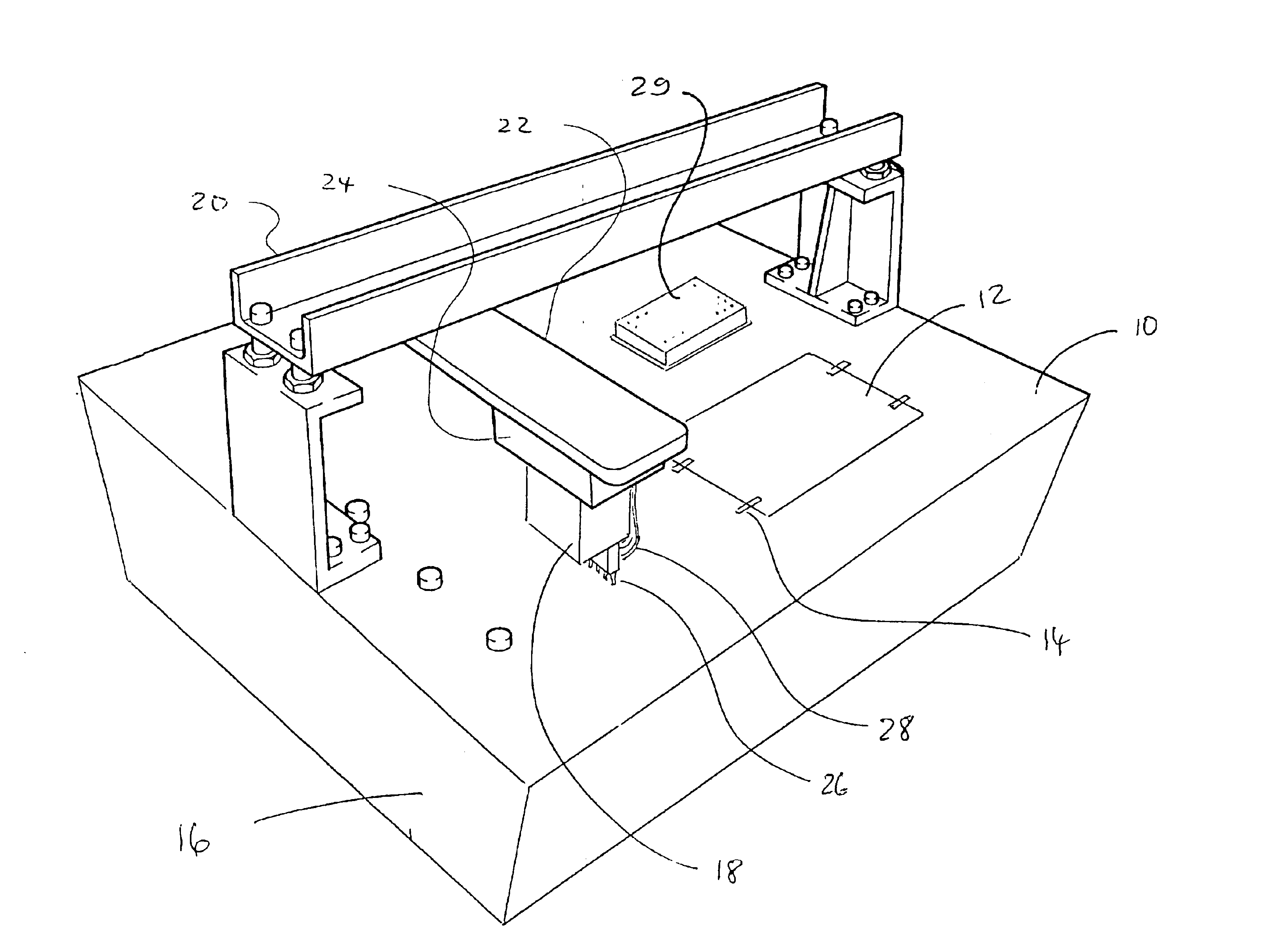
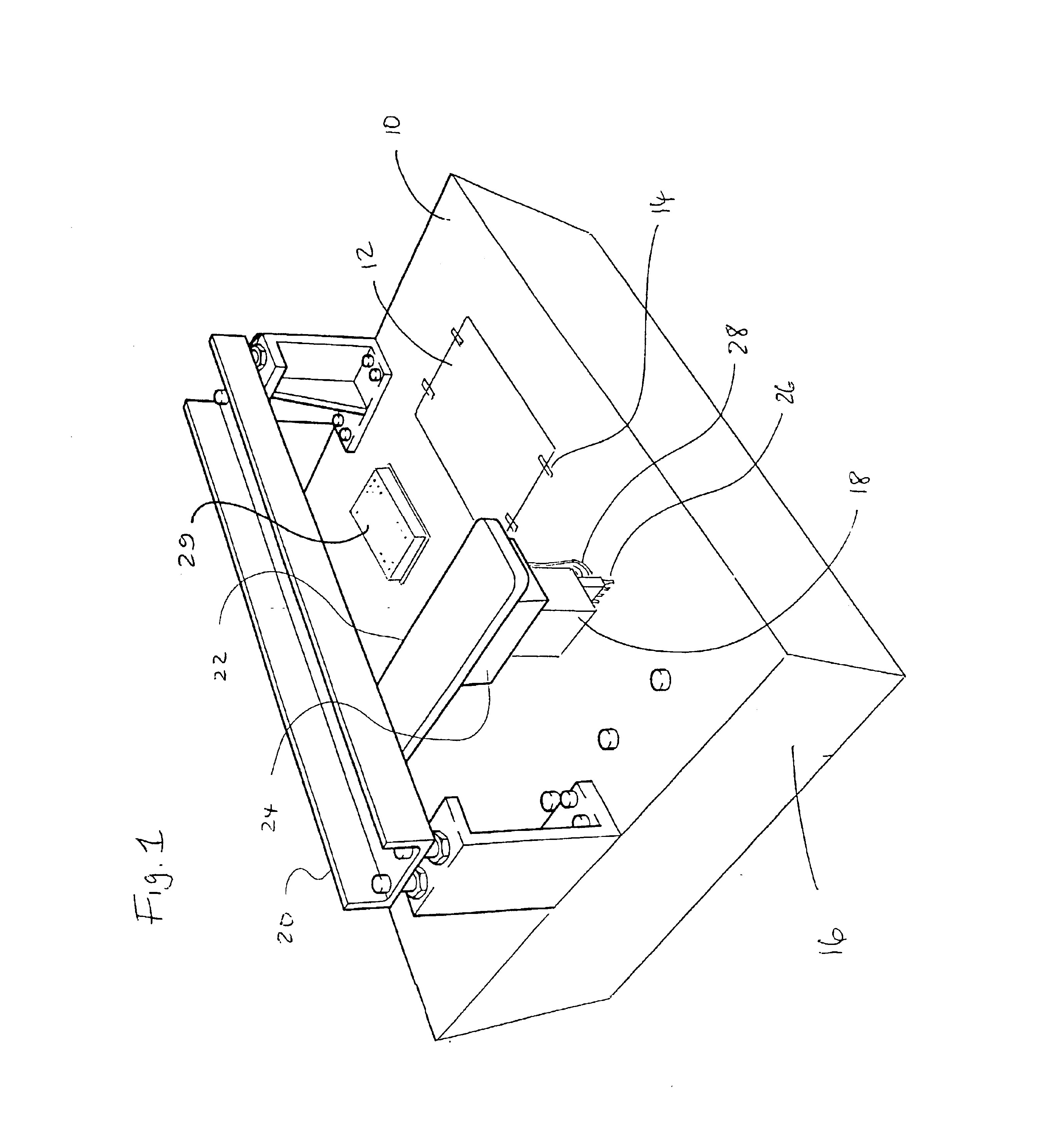
FIG. 1 is a perspective view of the lower part of an apparatus embodying the invention. The upper part is not shown in order to reveal the main bed 10 of the apparatus. A light table plate 12 made of a translucent material, known as opal acrylic, is mounted flush with the main bed. A set of clamps 14 (four in the figure) is provided around the periphery of the light table plate 12 for locating and securing gel dishes, such as Q-trays, on the light table. The light table plate is illuminated from below by optical equipment accommodated under the main bed in the space provided in the apparatus's main base 16.

The apparatus has a manipulation head 18, a gel coring head in the figure, which is movable over the main bed of the apparatus by x- y- and z-positioners 20, 22 and 24 respectively. The gel coring head illustrated comprises an array of gel corers 26, each gel corer having the form of a hollow pin connected to an air feed line. In one example, the head has a 1×8 array of corers wit...


PUM


Abstract

A robot for imaging and excision of two-dimensional fluorescent gels. An array detector is mounted in the roof of the robot to image down onto a gel dish placed on a light table. Fluorescence is excited by illuminating the light table from below with light emitting diodes mounted under the main bed of the apparatus. It is therefore possible to perform gel fluorescence analysis and coring (excision) using the same machine. The integration is based on a transmission mode optical design, distinct from prior art scanners and imagers which are based on reflection mode designs. This approach allows the conventional layout of a microarraying or picking robot to be maintained, avoiding unnecessary redesign of other robot functions associated with well plate and container handling. The apparatus may also be used for contrast imaging of non-fluorescent gels.

Description

BACKGROUND OF THE INVENTIONThe invention relates to imaging of gels stained with fluorescent material, in particular to imaging of two-dimensional gels such as protein gels, but also to imaging of one-dimensional gels, such as electrophoresis gels. The invention further relates to excision of gel material on the basis of its fluorescence.Protein gels are used in various biochemical processes. Proteins are manipulated in one or two dimensions in a gel. For example, manipulation may be in the form of protein migration, where migration rate depends on protein molecule size with the smallest proteins moving fastest. Another kind of manipulation is based on response to an electric field which can be used to force alkali and basic proteins to move in opposite directions with a migration rate that depends on the degree of alkalinity or acidity. So-called two-dimensional gels allow protein migration based on size and acidity to be performed in orthogonal directions in the same gel.To measur...

Claims


Application Information

Patent Timeline
IPC IPC(8): G01N27/447G01N21/64
CPCG01N21/6456G01N27/44721G01N27/44773
Inventor ATKINSON, GEORGE ROBERTWOODROUGH, ROBERT
Owner GENETIX LTD
Why Eureka
Try Eureka