
Barrier rib formation on substrate for plasma display panels and mold therefor

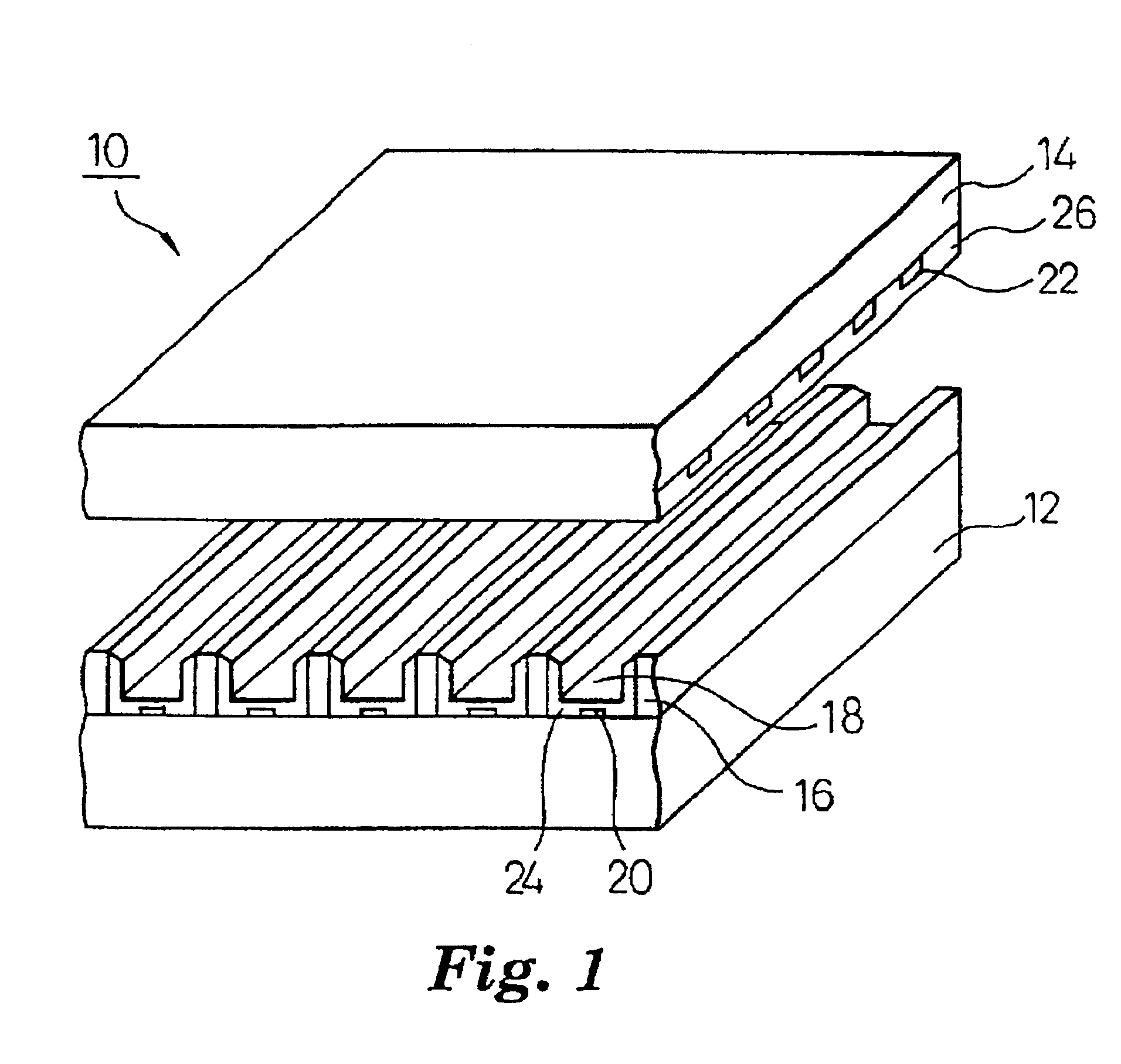
a technology of plasma display panels and substrates, which is applied in the manufacture of electrode systems, cold cathode manufacturing, and discharge tube/lamp manufacture, etc., can solve the problems of mold itself, base or rib breakage, and reduce production, so as to avoid the breakage of the base or rib

Inactive Publication Date: 2005-04-12
3M INNOVATIVE PROPERTIES CO
View PDF38 Cites 20 Cited by
  • Summary
  • Abstract
  • Description
  • Claims
  • Application Information

AI Technical Summary

Benefits of technology

It is an object of the present invention to provide a method of producing a substrate for PDP, capable of repeatedly using a mold with avoiding breakage of a base or a rib, and a mold used in the method.
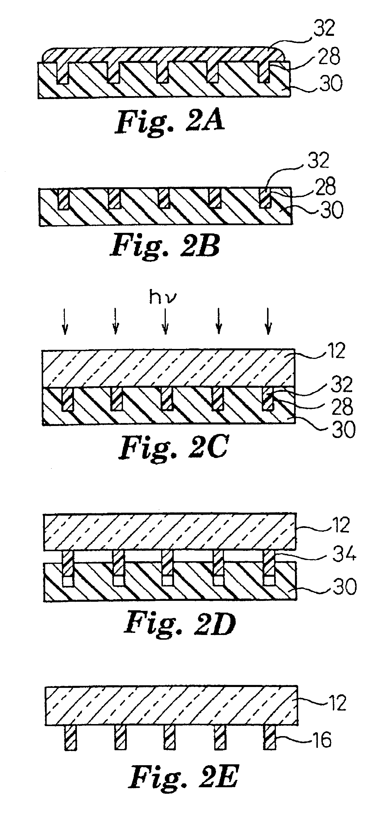
There is further provided the above method, which further comprises the step of irradiating the rib precursor composition filled in the mold at the peripheral portion of the base with light-having a wavelength shorter than that corresponding to the second absorption edge, thereby setting the rib precursor composition. According to such a method, as described in detail below, the rib molded article is adhered to the mold by the photosetting reaction between the unreacted secondary setting component in the mold and the first setting component in the rib precursor composition, thereby removing the rib molded article at the peripheral portion of the base, together with the mold, and therefore a step of removing the rib molded article at the peripheral portion of the base is not required.

Problems solved by technology

As a result, when the mold is removed from the rib, there is a fear of causing breakage of the base or rib, or breakage of the mold itself Such severe breakage often occurs when the rib is press-molded by using a mold made of glass, ceramic or metal as disclosed in Unexamined Patent Publication (KOKAI) No. 9-283017.
It is not preferred to leave the broken rib in the mold, since it is necessary to wash the mold every time the rib is made, thereby lowering the productivity.
However, the silicone resin is generally brittle.
Accordingly, it can not be expected to repeatedly use the mold made of the silicone resin for mass production.

Method used


Image

  • Barrier rib formation on substrate for plasma display panels and mold therefor
  • Barrier rib formation on substrate for plasma display panels and mold therefor
  • Barrier rib formation on substrate for plasma display panels and mold therefor

Examples


example 1

In this example, a photosensitive paste was prepared in the following procedure. First, 10 g of a bisphenol A diglycidyl ether methacrylic acid adduct (manufactured by Kyoei-sha Kagaku Co.) and 10 g of triethylene glycol dimethacrylate (manufactured by Wako Pure Chemical Industries Co.) were mixed to prepare a first photo-setting component. To this first photo-setting component, 0.2 g of a first photo-setting initiator of bis(2,4,6-trimethylbenzoyl)phenylphosphine oxide commercially available from Ciba Geigy Co. under the trade name of Irgacure 819, 20 g of 1,3-butanediol as a diluent, 0.2 g of phosphate propoxyalkyl polyol (POCA) as a surfactant and 0.1 g of Dappo SN357 (Sunnopco Co.) as an antifoamer were added. 80 g of a mixed powder (RFW-030) of lead glass (PbO—B2O3—SiO2) commercially available from Asahi Glass Co. and an inorganic oxide was dispersed in this solution. After the completion of the dispersion, the resulting paste were charged in a glass container and evacuation wa...

example 2

In this example, a photosensitive paste was prepared in the following procedure. First, 10 g of a bisphenol A diglycidyl ether methacrylic acid adduct (manufactured by Kyoei-sha Kagaku Co.) and 10 g of triethylene glycol dimethacrylate (manufactured by Wako Pure Chemical Industries Co.) were rixed to prepare a first photo-setting component. To this first photo-setting component, 0.2 g of a first phot-setting initiator of bis(2,4,6-trimethylbenzoyl)-phenylphosphine oxide commercially available from Ciba Geigy Co. under the trade name of Irgacure 819, 20 g of 1,3-butanediol as a diluent, 0.2 g of phosphate propoxyalkyl polyol (POCA) as a surfactant and 0.1 g of Dappo SN357 (Sunnopco Co.) as an antifoamer were added. 80 g of a mixed powder (RFW-030) of lead glass (PbO—B2O3—SiO2) commercially available from Asahi Glass Co. and an inorganic oxide was dispersed in this solution. After the completion of the dispersion, the resulting paste were charged in a glass container and evacuation wa...

example 3

A photosensitive paste was prepared in the following procedure. First, 24 g of γ-methacryloxypropylmethyldimethoxysilane (manufactured by Nippon Unicar Co.) as a first photo-setting component was prepared. In addition, 6 g of a mixed solution of an aqueous 0.01 N nitric acid solution and ethanol in a molar ratio of 2:1 was prepared. After these components were mixed and sufficiently stirred, the mixture was reacted by allowing to standing at 70° C. for 12 hours. Then, the reaction product was dried at 70° C., and water and alcohol were removed by evaporation.

To this liquid, 8 g of 2-hydroxyethyl methacrylate (manufactured by Wako Pure Chemical Industries Co.) was added to prepare a first setting component. Furthermore, 8 g of 1,3-butanediol (Wako Pure Chemical Industries Co.) as a diluent, 0.3 g of Irgacure 819 manufactured by Ciba Geigy Co. as a first photo-setting initiator, 0.2 g POCA (phosphate propoxyalkyl polyol) as a surfactant and 0.1 g of Dappo SN357 (Sunnopco Co.) as an an...


PUM

PropertyMeasurementUnit
Areaaaaaaaaaaa
Transparencyaaaaaaaaaa

Abstract

A method of producing a substrate (12) for a plasma display panel, which comprises the steps of: contacting a rib precursor composition (32) containing a first photo-setting initiator having a first absorption edge and a first photo-setting component, closely with a base (12); filling a mold (30), obtained by photo-setting of a second photo-setting component in a presence of a second photo-setting initiator having a second absorption edge whose wavelength is shorter than that corresponding to the first absorption edge of the first photo-setting initiator, with the rib precursor composition (32); irradiating the rib precursor composition (32) with light having a wavelength longer than that corresponding to the second absorption edge to set the rib precursor composition (32), thereby forming a rib (34) on the base (12); and removing the mold (30) from the resulting base (12) on which the rib (34) is formed.

Description

CROSS REFERENCE TO RELATED APPLICATIONSThis application claims priority from Japan Application No. 11-259318, filed Sep. 13, 1999.FIELD OF UTILIZATION IN INDUSTRYThe present invention relates to a method of producing a substrate for plasma display panels (hereinafter also referred to as “PDP”, merely) and a mold used in the method.RELATED ARTPDP is expected to be used as a thin large-image display device. Generally, PDP is equipped with a so-called substrate for PDP. Typical substrate for PDP is composed of a pair of glass flat plates facing each other at a distance via a rib having a predetermined dimension (also referred to as a barrier rib, partition or barrier). In this case, such a rib separates space between a pair of glass plates into cells in an air-tight manner to form a plurality of discharge display cells capable of containing a discharge gas such as neon, helium or xenon.Various suggestions have been made to produce and provide the rib. For example, a method of using a m...

Claims


Application Information

Patent Timeline
IPC IPC(8): B29C35/08H01J9/24
CPCH01J9/242H01J2211/36
Inventor YOKOYMA, CHIKAUMISUGIMOTO, TAKAKIYODA, AKIRA
Owner 3M INNOVATIVE PROPERTIES CO
Learn More