Recovering apparatus for recovering a status of an ink jet recording head

Inactive Publication Date: 2005-03-29
COPYER
View PDF39 Cites 0 Cited by
  • Summary
  • Abstract
  • Description
  • Claims
  • Application Information

AI Technical Summary

Benefits of technology

An object of the present invention is to provide a recovering apparatus which can wipe the ink ejecting ports forming plane of ink jet head effectively.
Another object of the present invention is to provide a small printer which has a plurality of ink jet heads and a plurality of recovering means maintaining the ink ejecting status of the heads under good condition, and which has higher printing productivity because of the small moving range of the heads and the recovering means.
A large-sized liquid droplet can be absorbed in the absorbing member by sufficiently reducing a gap between ink ejecting ports of ink jet head and the absorbing member.
Further, since the absorbing member is disposed in a cap serving to cap the ink ejecting ports forming plane of the ink jet head, large ink droplets or water droplets adhering to the ink ejecting port forming plane due to deposition of ink mist or dewing on the same can be absorbed in the absorbing member in the capping state. The ink ejecting ports forming plane can be maintained under a good condition by bringing a wiping member in contact with the ink ejecting ports forming plane so as to wipe the plane with the wiping member.

Problems solved by technology

A label printer having an ink jet printing system utilized therefor has not been put in practical use till now.
Lately, there is a tendency that the number of bar codes becomes short.
This leads to problem that a size of the power source is enlarged, and the color label printer is produced at an increased cost.
Therefore, in contrast with a printer operable with cut printing papers like an ordinary office-use printer, it is very difficult to arrange a recovering system and design a recovering sequence.
In this connection, it is also very difficult to compactly design and construct a printing head, a recovering system unit, an ink feeding system, and a printing medium conveying system.

Method used


Image

  • Recovering apparatus for recovering a status of an ink jet recording head
  • Recovering apparatus for recovering a status of an ink jet recording head
  • Recovering apparatus for recovering a status of an ink jet recording head

Examples


Embodiment Construction

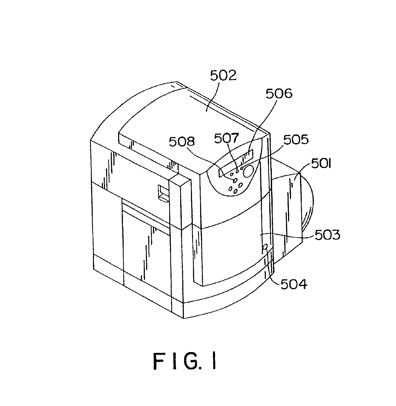
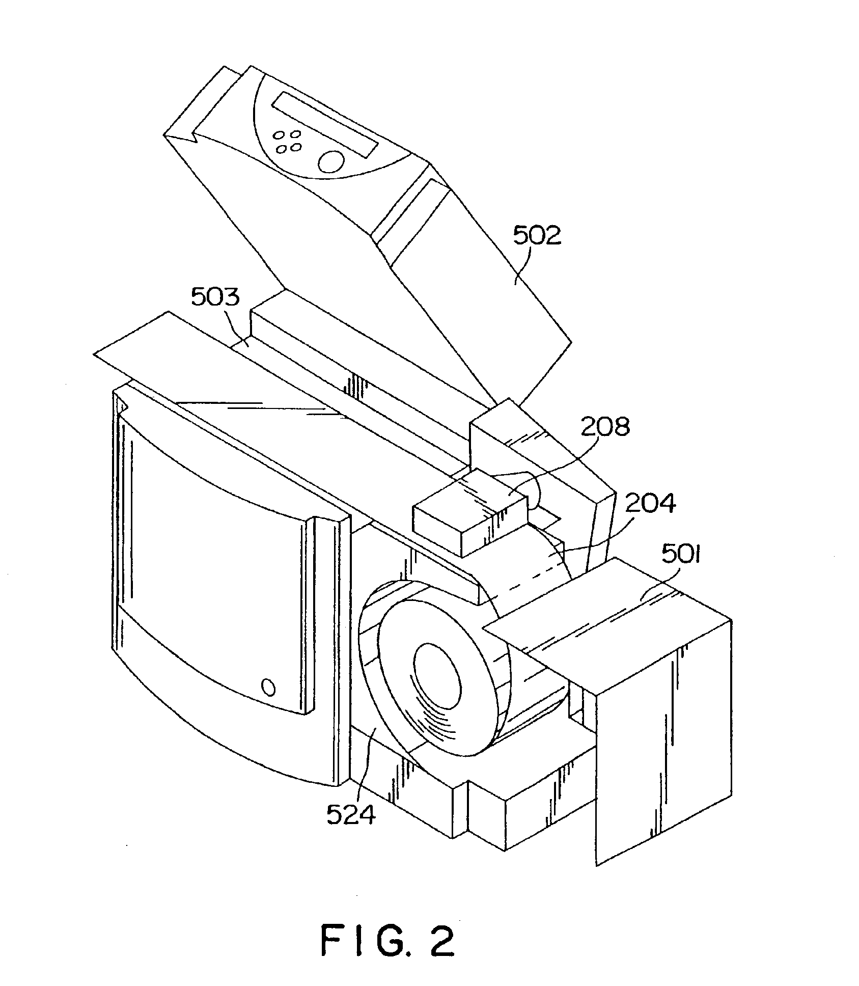
The present invention will now be described in detail hereinafter with respect to the following items with reference to the accompanying drawings which illustrate preferred embodiments thereof.(1) Outline of the structure of a label printer to which the present invention is applied (see FIG. 1 to FIG. 3)(2) Printing head station (see FIG. 4 to FIG. 11)(2.1) Whole structure of the printing head station (see FIG. 4 and FIG. 6)(2.2) Head block (see FIG. 6)(2.3) Recovering system unit (see FIG. 7 to FIG. 10)(2.4) Cooling unit (see FIG. 11)(3) Printing medium conveying mechanism (see FIG. 12 to FIG. 14)(3.1) Roll feeding unit(3.2) Conveying unit(3.3) Cutter unit(3.4) Other embodiment of the roll feeding unit(4) Ink system (see FIG. 15 to FIG. 19)(5) Hardware for a controlling system (see FIG. 20)(6) Precedent treatment for blank paper and subsequent treatment for blank paper(7) Recovering treatment for a printing head (see FIG. 21 to FIG. 35)(7.1) Recovering treatment to be conducted whe...


PUM


Abstract

In a recovering apparatus for recovering ink ejecting ports forming a plane of an ink jet head, an ink absorbing member is disposed inward of a cap and proximate to the ink ejecting ports, facing the ink ejecting ports at a predetermined distance therefrom. Large ink droplets or water droplets adhering to the ink ejecting ports are then absorbed in the absorbing member. Thereafter, the plane of the ink jet heads with the ink ejecting ports is cleanly wiped by a wiping member, thereby preventing scattering of ink droplets or water droplets away from the ink ejecting ports. A trough is located adjacent to each head, and the recovering apparatus is disposed with respect to the trough so that a distance between the recovering apparatus and the ink jet head can be reduced, thereby permitting a compact arrangement of the recovering apparatus and the ink jet head.

Description

FIELD OF THE INVENTIONThe present invention relates generally to a label printer widely used in the field of, e.g., POS (point of sale), FA (factory automation), physical distribution or the like. More particularly, the present invention relates to a label printer having an ink jet printing system employed therefor.DESCRIPTION OF THE RELATED ARTA label printer having an ink jet printing system utilized therefor has not been put in practical use till now. General advantages obtainable from ink jet recording are as noted below. Specifically, one of them is that ink jet printing is effected with excellent quietness attributable to no contact with a printing medium, other one is that ink jet printing is performed at a high speed, another one is that ink jet printing can be achieved at a high density, further one is that ink jet color printing can easily be realized, and an ink jet printing apparatus can be designed with small dimensions.A conventional label printer is usually constructe...

Claims


Application Information

Patent Timeline
IPC IPC(8): B41J11/48B41J2/17B41J2/165B41J3/407B41J2/175B41J15/04B41J29/377
CPCB41J2/16547B41J2/16588B41J2/1707B41J29/377B41J3/4075B41J11/48B41J15/048B41J2/175
Inventor FUJIMOTO, HITOSHISUGIYAMA, KATSUMINAITO, MASATAKAIKKATAI, MASATOSHIHARADA, TSUTOMUFUKUSHIMA, TATSUYATAMURA, TAKEFUMIMIKOSHIBA, TSUYOSHI
Owner COPYER
Why Eureka
Try Eureka