
Thermal-sprayed tooling

a tooling and spraying technology, applied in the field of tools, can solve the problems of inability to manufacture very large molds, inability to meet the requirements of large molds, and inability to meet the requirements of large molds, and achieve the effects of simple techniques, improved heat transfer, and economic manufacturing

Inactive Publication Date: 2005-03-29
GMIC CORP
View PDF16 Cites 10 Cited by
  • Summary
  • Abstract
  • Description
  • Claims
  • Application Information

AI Technical Summary

Benefits of technology

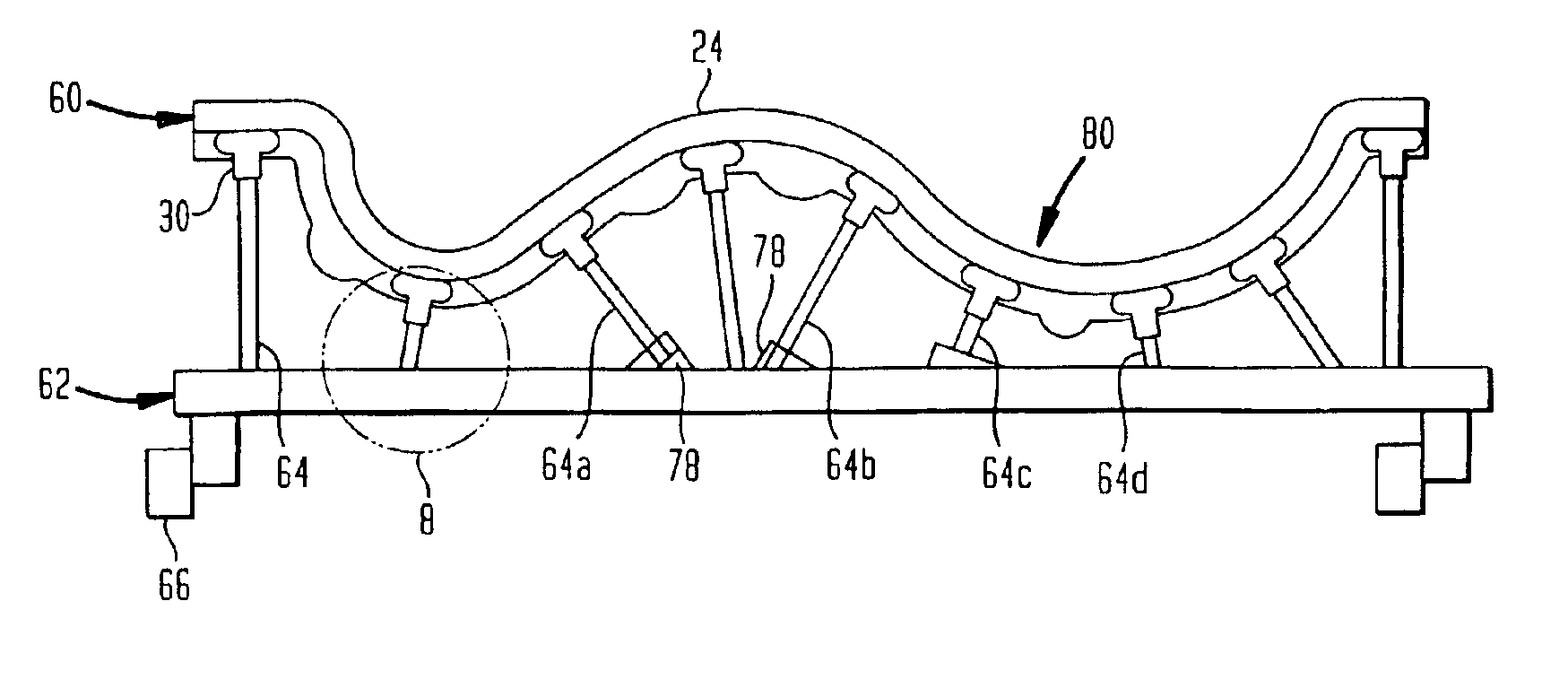
The rods and base form a strong, light-weight assembly which provides support at numerous locations on the shell. Desirably, the rods are connected to the base by adjustable attachments which can make secure connections between the rods and base despite deviations in the positioning of the rods. Thus, the rods can be engaged with the mounting elements and base even if the mounting elements are not placed with extreme precision. The entire assembly can be fabricated economically, using simple techniques.

Problems solved by technology

These techniques are impractical in the case of very large molds, such as those having dimensions of about a meter (about three feet) or more.
Composite parts used in airframes must meet exacting standards for fit and finish and often incorporate complex curved surfaces.
The cost of machining very large molds from solid blocks of these materials is prohibitive.
The need for such support is particularly great in the case of very large molds, where the weight of the shell, the weight of the materials placed in the shell during a molding process, and the pressure applied to the molding composition during the molding process all can cause deformation of the mold.
All of these factors, taken together, have presented a significant engineering challenge.
In some cases, local heat transfer problems limit the production rate and the part quality.
For example, parts having diverse geometric features such as curves, corners and the like, and parts having relatively thin sections and relatively thick sections, do not cure uniformly.
This limits the rate at which parts can be formed in the mold and can cause product defects such as warpage.

Method used


Image

  • Thermal-sprayed tooling
  • Thermal-sprayed tooling
  • Thermal-sprayed tooling

Examples


Embodiment Construction

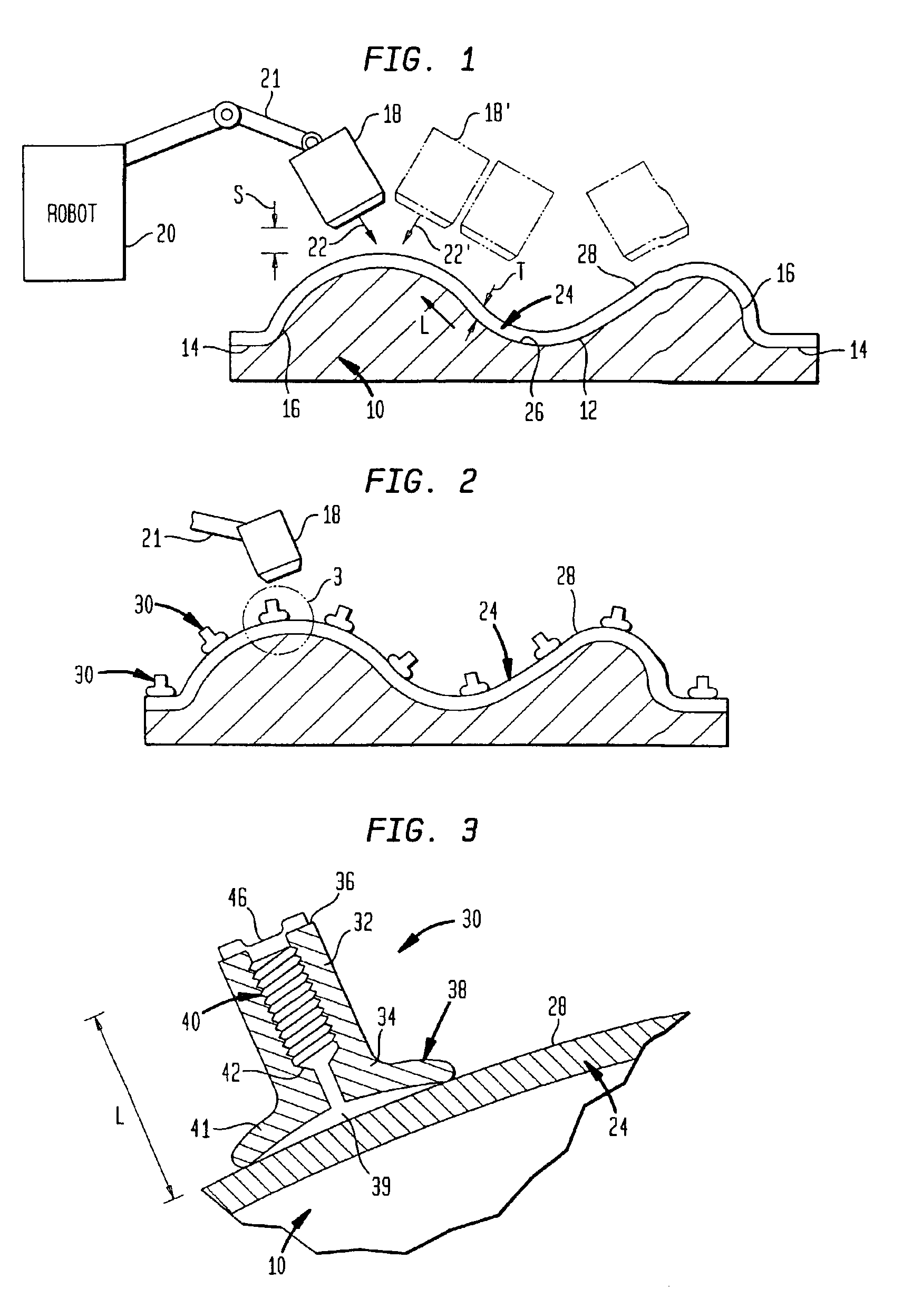
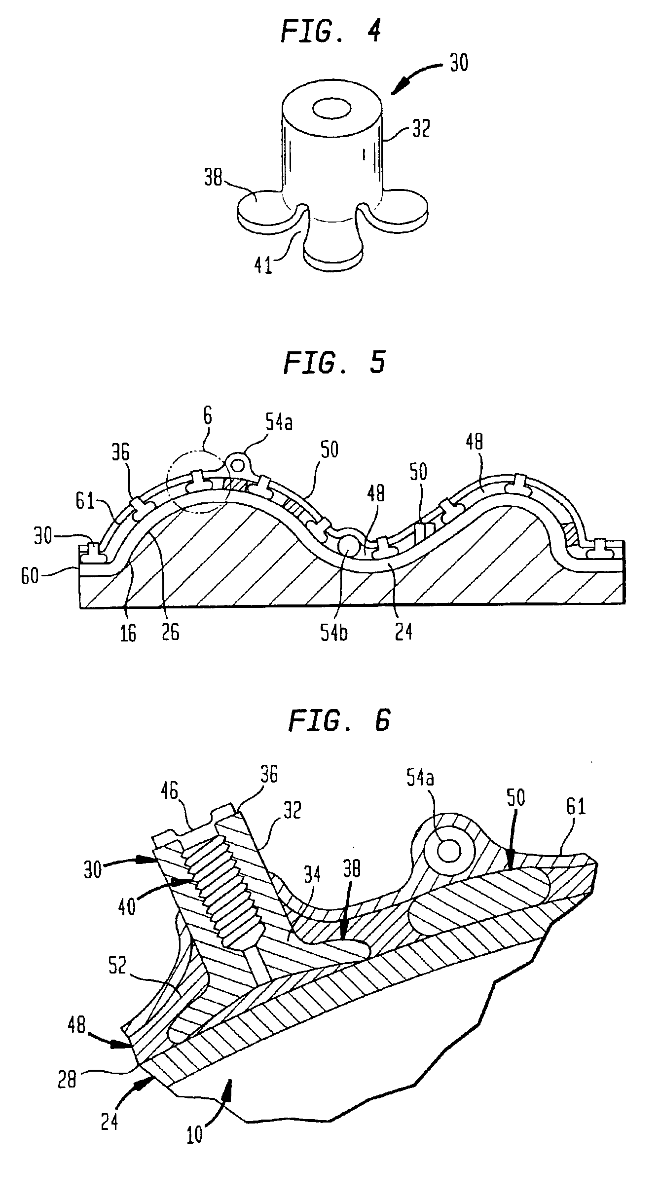
A process in accordance with one embodiment of the invention uses a matrix 10 having an active surface 12 with a shape corresponding to the shape of the part to be molded. As described in greater detail in the '267 patent, the matrix desirably also includes edge regions 14 projecting outwardly from the active surface and side walls 16 extending between the edge regions and active surface 12. The matrix 10 can be formed from essentially from any material having useful structural strength at the temperatures attained by the matrix during application of the sprayed metal, typically on the order of 220° F. (104° C.). The matrix can be formed by any conventional process. For example, high-temperature epoxy composite tooling compounds can be cast to shape using a master tool (not shown). Readily machinable materials such as polymeric materials, metals such as aluminum or brass and graphite may be machined to shape using conventional methods such as numerically controlled machining methods...


PUM

PropertyMeasurementUnit
areaaaaaaaaaaa
temperaturesaaaaaaaaaa
standoff distanceaaaaaaaaaa

Abstract

A metallic shell used, for example as a mold, is formed by spray deposition connected to a base by rods or other supports connected to mounting elements which are incorporated in the shell during the deposition process. The shell can incorporate different metals to provide different thermal conductivity in various regions.

Description

FIELD OF THE INVENTIONThe present invention relates to tools such as molds fabricated by thermal spraying of metals.BACKGROUND OF THE INVENTIONIndustrial processes such as molding and lay up of composite materials, thermoforming, injection molding and reaction injection molding require tools having a shape specific to the article to be made. For example, a composite article can be formed in a mold having a shape corresponding to the shape of the desired article by laying up fibers and a matrix composition such as an epoxy or other polymeric material on the surface of the mold and curing the polymer composition. In some cases, the fibers and composition are held between two mating mold parts so that the fibers and composition are squeezed between the surfaces of the mold parts. In reaction injection molding, two or more mating mold parts are brought together to form a substantially closed cavity and a reactive polymer composition is placed within the cavity and cured to form a shape ...

Claims


Application Information

Patent Timeline
Patent Type & Authority Patents(United States)
IPC IPC(8): B22C9/06B22F3/00B22F3/115B22F5/00B29C33/30B29C33/38C23C4/00
CPCB22C9/061B22F3/115C23C4/00B29C33/3828B29C33/307B22F5/007B22F7/08B29C33/308B22F2999/00B22F2998/10
Inventor COVINO, CHARLES P.
Owner GMIC CORP
Learn More