Combined fuel cell and fuel combustion power generation systems

a fuel cell and power generation technology, applied in the field of power plant systems, can solve the problems of limited prior art development of fuel cell and fuel combustion

Inactive Publication Date: 2005-03-22
CLEAN ENERGY SYST
View PDF203 Cites 146 Cited by
  • Summary
  • Abstract
  • Description
  • Claims
  • Application Information

AI Technical Summary

Problems solved by technology

While combustion based power systems and fuel cell based power systems are well known in the art, their development in the prior art has been limited to primarily their advancement independent of each other.

Method used


Image

  • Combined fuel cell and fuel combustion power generation systems
  • Combined fuel cell and fuel combustion power generation systems
  • Combined fuel cell and fuel combustion power generation systems

Examples


Embodiment Construction

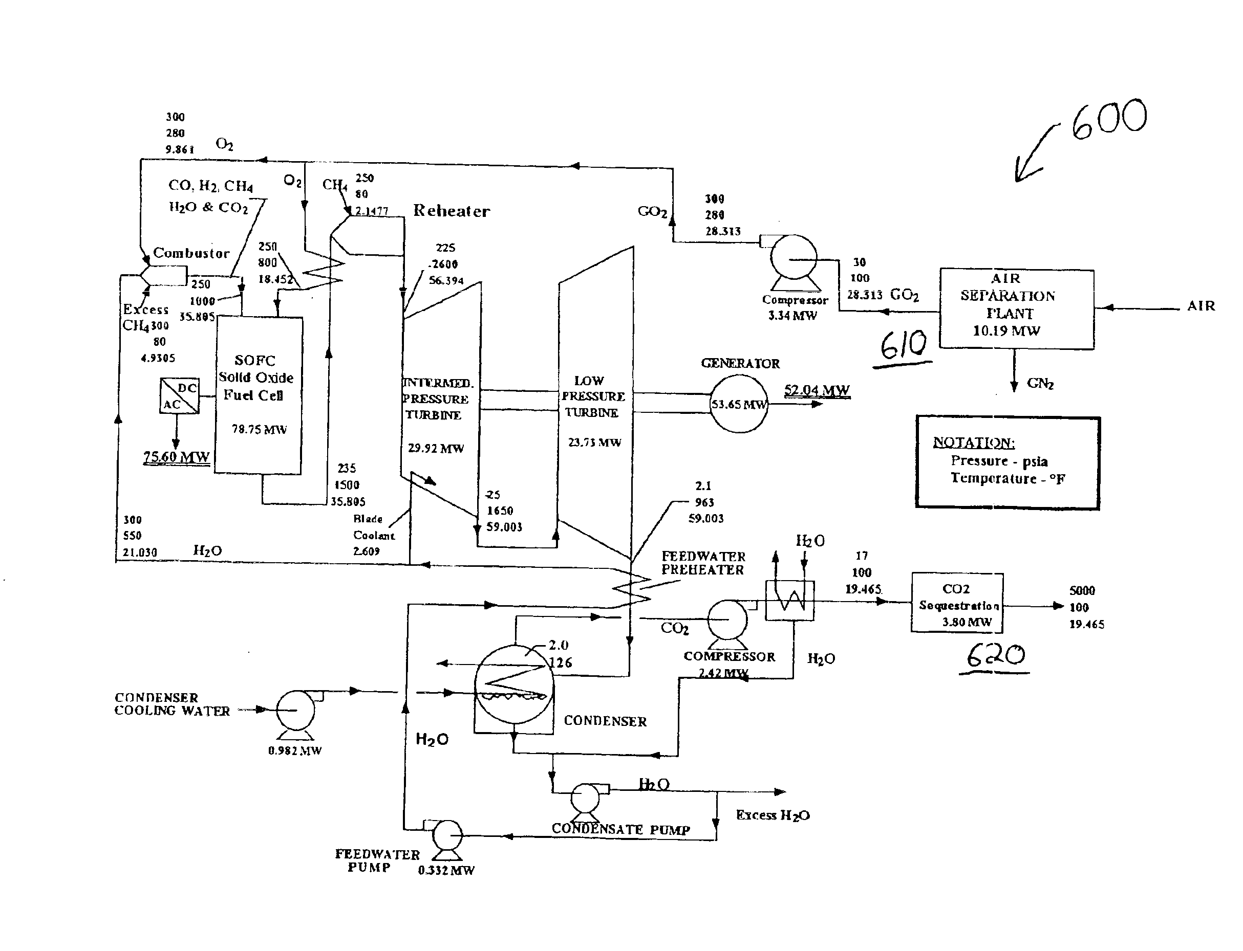
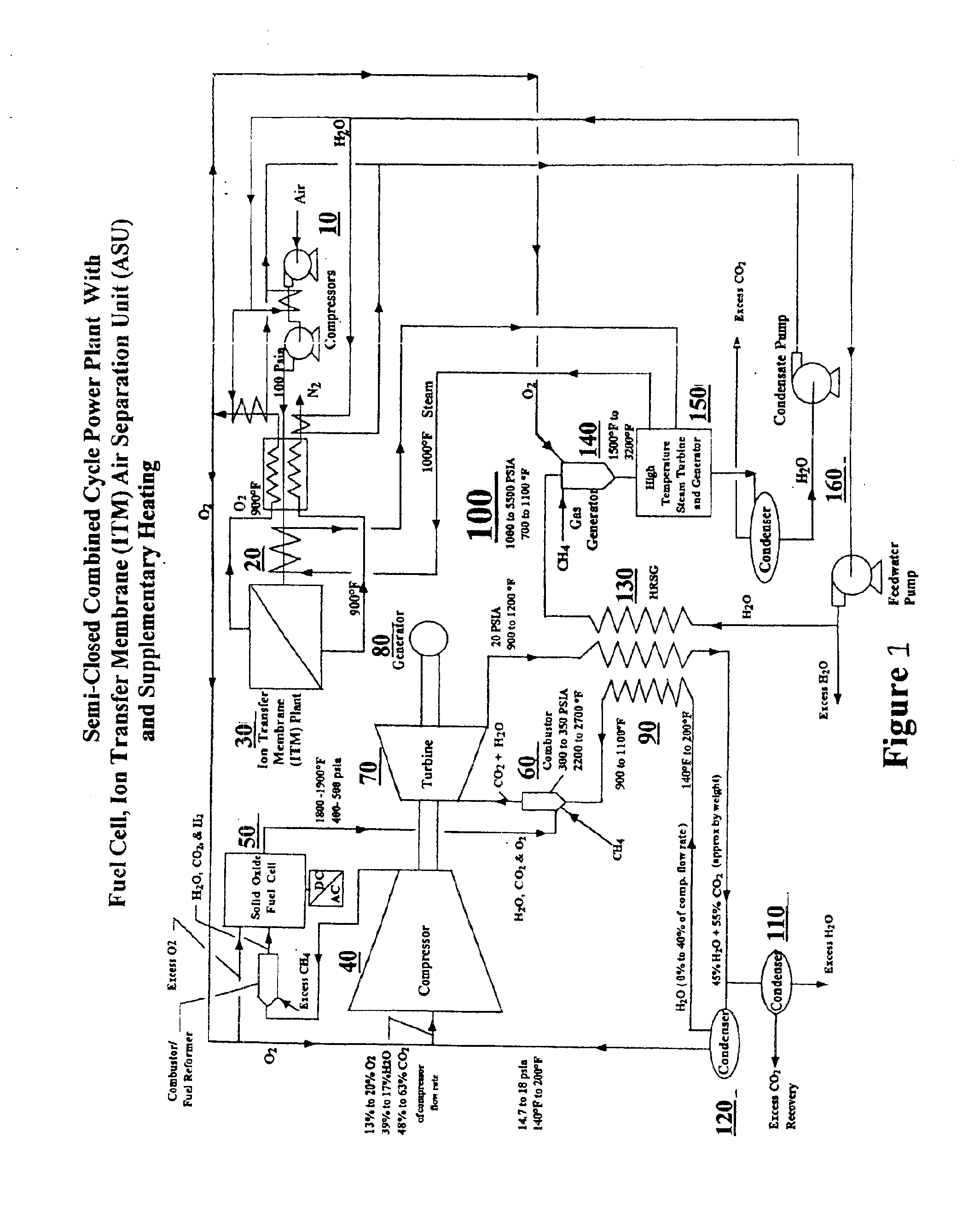
FIG. 1 illustrates the concept of this invention with a non-polluting efficient electrical energy power plant 100, comprising an air induction subsystem 10, air preheating subsystem 20, an ion membrane air separation subsystem 30, a gas compression subsystem 40, a fuel cell subsystem 50, a combustor subsystem 60, a gas turbine drive subsystem 70, an electric energy generation subsystem 80, a heat recovery subsystem 90, a H2O / CO2 separation subsystem 110, a gas separation / water management subsystem 120, a heat recovery steam generator subsystem 130, a gas generator subsystem 140, a steam turbine / generator subsystem 150, and a condenser / water management subsystem 160. Many of these subsystems are described in detail in either copending U.S. patent application Ser. Nos. 09 / 855,223, 09 / 855,224 and 09 / 855,237 or in U.S. Pat. Nos. 6,170,264 and 6,247,316; each of these references hereby incorporated by reference.

The air induction subsystem 10 feeds and controls the air supply to generate ...


PUM

PropertyMeasurementUnit
electrical poweraaaaaaaaaa
temperatureaaaaaaaaaa
pressureaaaaaaaaaa

Abstract

A power generation system is provided which converts chemical energy in one or more fuels into electrical and / or mechanical power. The system includes both fuel cells to directly convert electrical energy in a fuel into electrical power and at lest one combustor and expander to generate mechanical power, optionally than converted to electrical power in a generator. Fuel cell products disclosed from the fuel cell are entered into the combustor to be heated along with products of combustion created in the combustor and expanded in the expander along with the products of combustion.

Description

FIELD OF THE INVENTIONThe following invention relates to power plant systems which generate power by releasing energy by reaction of a fuel with an oxidizer. More particularly, this invention relates to power systems which both react oxygen with a hydrogen containing fuel within a fuel cell and combust oxygen with a hydrogen containing fuel in a combustor to convert chemical energy stored in the fuel and the oxidizer into electrical and / or mechanical power.BACKGROUND OF THE INVENTIONFundamental to all chemical reactions, which react two or more reactants together to produce products, is the release of energy (in exothermic reactions) or the absorption of energy (in endothermic reactions) associated with a particular chemical reaction. By properly controlling chemical reactions of an exothermic variety, energy can be released and converted into useful electrical or mechanical power.One common form of exothermic chemical reaction is a combustion reaction. In a combustion reaction, a f...

Claims


Application Information

Patent Timeline
Patent Type & Authority Patents(United States)
IPC IPC(8): H01M8/06H01M8/04H01M8/12
CPCH01M8/04022H01M8/04097H01M8/0606H01M8/0662H01M8/04156H01M8/12Y02E60/563H01M2250/407Y02E20/14Y02E20/16Y02E60/50Y02E60/525H01M2008/1293Y02P90/40
Inventor VITERI, FERMINANDERSON, ROGER E.
Owner CLEAN ENERGY SYST
Why Eureka
Try Eureka