
Fuel mixing control for fuel cell power plants operating on multiple fuels

a fuel cell and power plant technology, applied in electrochemical generators, greenhouse gas reduction, chemistry apparatus and processes, etc., can solve the problems of csa b>12/b> to shut down or reduce power, and the scheme for determining relative amounts of fuels has not been addressed

Inactive Publication Date: 2005-05-10
INT FUEL CELLS
View PDF3 Cites 13 Cited by
  • Summary
  • Abstract
  • Description
  • Claims
  • Application Information

AI Technical Summary

Benefits of technology

[0010]It is a further object of the invention to provide a control arrangement for mixing fuels i

Problems solved by technology

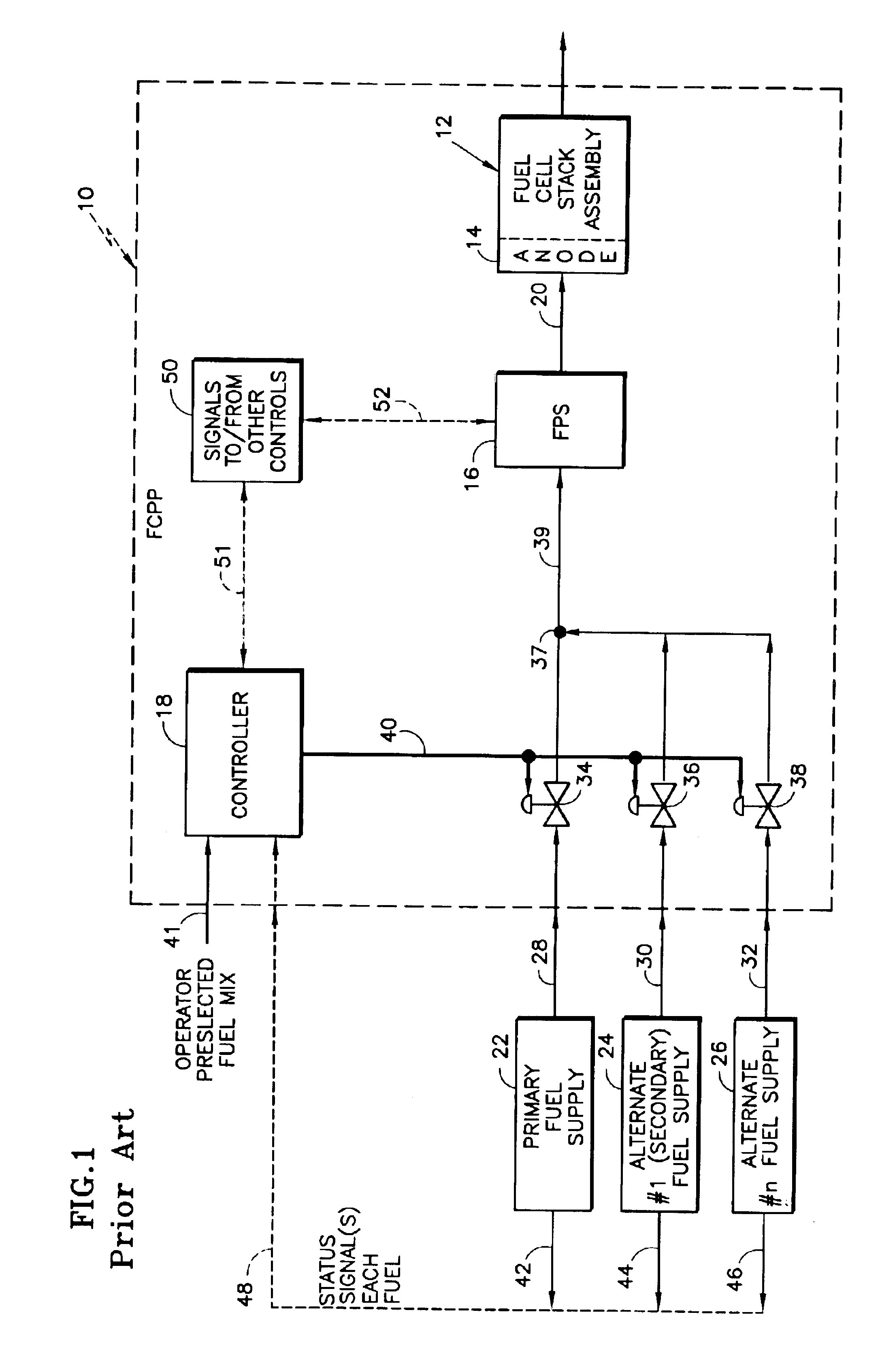
Although the system described above with reference to FIG. 1 has the capability to use alternate fuels, either separately or in some pre-selected mixed combination, the particular selection of fuels and the scheme for determining their relative amounts has not been addressed.
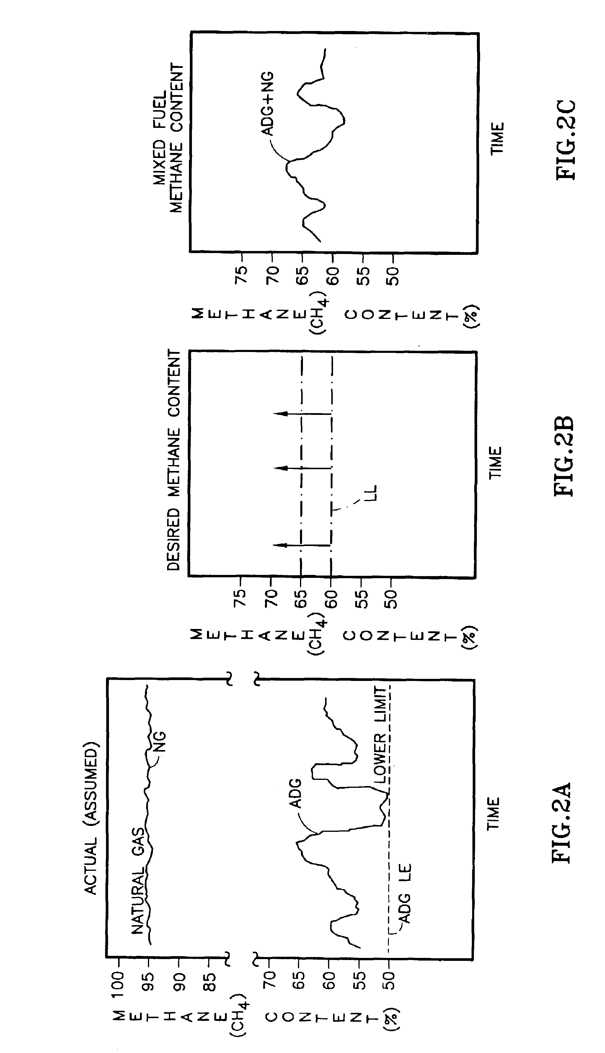
In this latter regard, if the hydrogen content of one or more of the fuels in a mix of multiple fuel sources is sufficiently variable during operation, failure to accommodate or compensate for such variation may cause the CSA 12 to shut down or reduce power in the event the hydrogen content is too low during a “variation”.
While there may be significant advantages, such as cost, etc., to the use of ADG as the sole fuel source, the aforementioned limitations may preclude that.
Alternatively, the use of another fuel source in combination with the ADG continues to present some problems because of the uncertainty of the actual level of equivalent H2 content of the ADG at any particular time.
This latter problem exists with respect to any combination of fuel sources where the H2 equivalent content of at least one of the fuels is not known and / or is variable.

Method used


Image

  • Fuel mixing control for fuel cell power plants operating on multiple fuels
  • Fuel mixing control for fuel cell power plants operating on multiple fuels
  • Fuel mixing control for fuel cell power plants operating on multiple fuels

Examples


Embodiment Construction

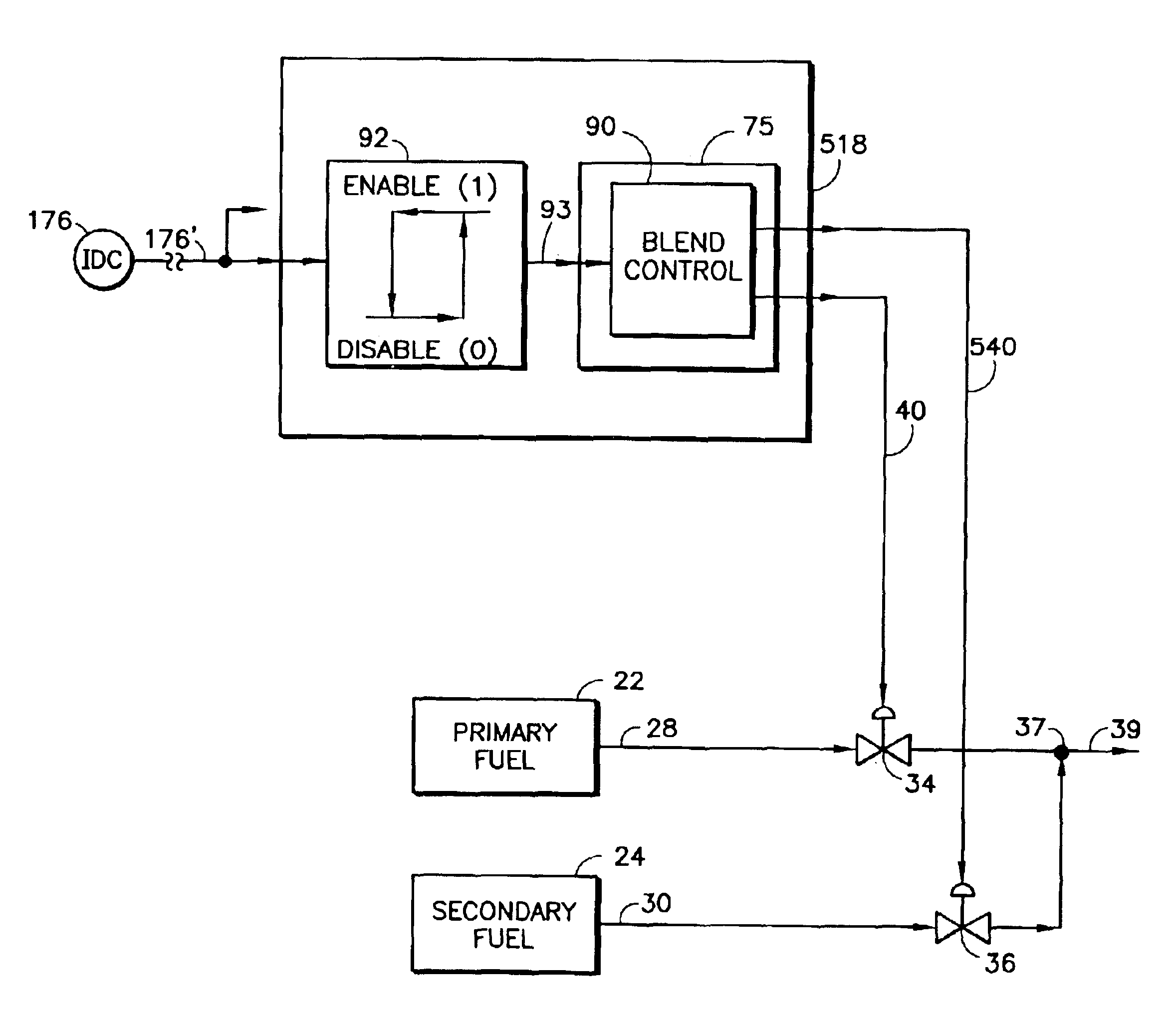
[0024]Referring to the Drawings, FIG. 1 depicts an existing fuel cell power plant having capability for using a hydrogen-containing primary fuel such as natural gas, and various alternate hydrogen-containing fuels, either alone or mixed, as determined by pre-selected settings, as previously described in the Background Art. In the main, much of the apparatus described and depicted in FIG. 1 of the Background Art is similarly used with respect to the invention to be described following, and thus, reference will be made to that structure using the reference numbers appearing in FIG. 1. Departure from that convention will be made only where necessary to emphasize and describe differences between the prior art and the present invention.

[0025]Because in many circumstances the availability and “cost” of ADG (or other similar fuels) may make it more attractive than other hydrogen-containing fuels, such as natural gas, there is incentive to make it the sole, or at least primary, fuel source ...


PUM


Abstract

Fuel mixing control arrangements are provided for fuel cell power plants (10) operating on multiple fuels (22, 24, 26). A fuel delivery system (16) supplies hydrogen-rich fuel (20) to the cell stack assembly (CSA) (12) after controlled mixing of a primary fuel (22) and at least a secondary fuel (24), each having a respective “equivalent hydrogen (H2) content”. The relative amounts of the primary fuel (22) and secondary fuel (24) mixed are regulated (18, 34, 36) to provide at least a minimum level (LL) of hydrogen-rich fuel having an equivalent hydrogen content sufficient for normal operation of the CSA (12). The primary fuel (22) is a bio-gas or the like having a limited, possibly variable, equivalent H2 content, and the secondary fuel (22) has a greater and relatively constant equivalent H2 content and is mixed with the primary fuel in an economic, constant relationship that assures adequate performance of the CSA (12). One or more parameters (IDC, P, V, E. C.) of the operating power plant (10) related to the equivalent H2 content of at least the primary fuel may be sensed (72, 26, 78, 84, 176) and used to control (18, 36) the relative amounts of secondary and primary fuels (22, 24) mixed in response thereto.

Description

TECHNICAL FIELD[0001]This invention relates to fuel cell power plants, and more particularly to fueling such fuel cell power plants. More particularly still, the invention relates to the operation of fuel cell power plants from multiple fuel sources.BACKGROUND ART[0002]The fuel cell stack assembly(ies) of most fuel cell power plants is fueled by hydrogen, or a hydrogen-rich fuel. The sources of such hydrogen are numerous and may include derivation from water, as by hydrolysis, or from solid storage, as from hydrides, but the most common forms are via hydrogen-rich gasses. Perhaps the most common source is from the hydrogen contained in the hydrogen-rich methane (CH4) of natural gas. Other hydrocarbons, such as propane, butane, methanol, ethanol, and various petroleum derivatives, including reformulated gasoline, are also good sources of hydrogen. Still further, other types of organic materials may be processed, as by active digestion and / or natural decomposition, to yield hydrogen-r...

Claims


Application Information

Patent Timeline
IPC IPC(8): C01B3/02C01B3/00H01M8/04H01M8/06H02J
CPCH01M8/04089Y02E70/20Y02E60/50H01M8/0612H01M8/04C01B3/02
Inventor ROCHE, ROBERT P.MARGIOTT, PAUL R.TROCCIOLA, JOHN C.
Owner INT FUEL CELLS
Learn More