
Single cell and stack structure for solid oxide fuel cell stacks

a fuel cell and single cell technology, applied in the field of solid oxide fuel cells, can solve the problems of difficult production, less likely to be practicably used, and gas or oxidizing gas to permeate,

Inactive Publication Date: 2005-03-08
KOREA ELECTRIC POWER CORP
View PDF3 Cites 23 Cited by
  • Summary
  • Abstract
  • Description
  • Claims
  • Application Information

AI Technical Summary

Benefits of technology

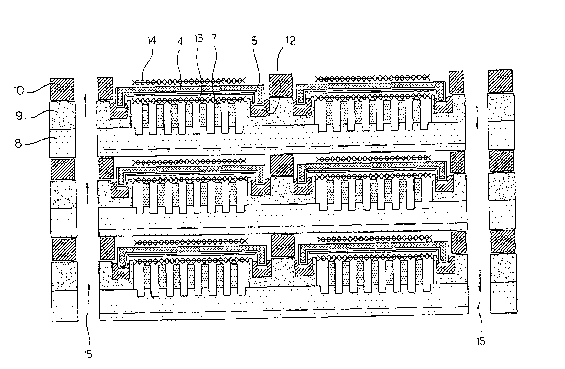
In the SOFC stack of this invention, the fuel gas and the oxidizing gas are free from being mixed together due to an improved gas sealing structure. The SOFC stack is thus free from the stress due to a difference in coefficient of thermal expansion between the single cells and the separating plate when the temperature of the stack is raised or lowered. Since the sealant is stably kept within the sealing grooves regardless of an environmental change, the SOFC stack is stably operated without being affected in performance when the temperature of the stack is raised or lowered. When the SOFC stack is assembled, the bent support portions of the single cells are precisely seated in the sealing grooves of the separating plate. The single cells are thus stably held within the SOFC stack irrespective of external impact or thermal stress. This finally lengthens the expected life span of the SOFC stack, improves the durability and the operational reliability of the stack, and allows a user to more easily repair the stack when necessary.

Problems solved by technology

In addition, the electrolyte substrate, or the intermediate layer of the single cell, preferably has a dense structure which does not allow fuel gas or oxidizing gas to permeate into the electrolyte or to be mixed together.
However, such a tubular type SOFC is problematic in that it is very difficult to produce and is less likely to be practically used.
However, the tubular type SOFC is problematic in that it has a low power density in comparison with the planar type SOFC or the monolithic type SOFC.
This finally forces the EVD equipment to be large-sized and increases the equipment cost.
Furthermore, a multi-step process has to be used for producing such a tubular type SOFC, thus increasing the production cost of single cells.
However, the known technique of producing ceramic thin plates only provides a square electrolyte plate having a dimension of about 10×10 cm or about 20×20 cm, the electrolyte plate being used as an electrode support plate.
However, such a highly gas sealing effect is very difficult to be accomplished during the process of producing the grid array stack, and so the requirement for the highly gas sealing effect stands in the way of practical use of such planar type SOFCs.

Method used


Image

  • Single cell and stack structure for solid oxide fuel cell stacks
  • Single cell and stack structure for solid oxide fuel cell stacks
  • Single cell and stack structure for solid oxide fuel cell stacks

Examples


example 1

A Process of Producing a Fuel Electrode (Anode) Support Type Single Cell Which is Bent Downwardly at Four Sides, and a Process of Producing an SOFC Stack Using Such Single Cells

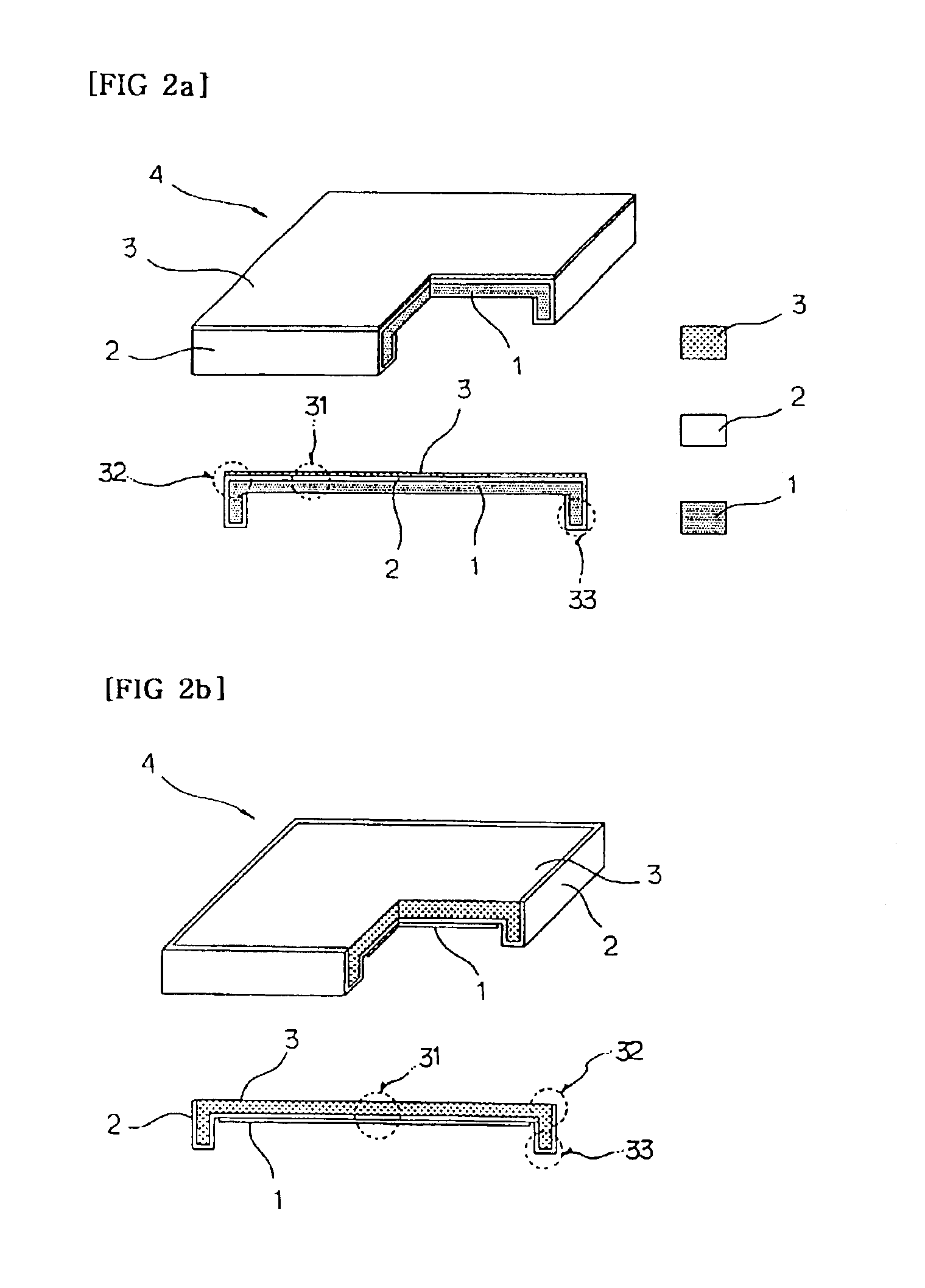
In order to produce a desired fuel electrode (anode) support type single cell, NiO powder and yittria stabilized zirconia power (ZrO2+8Y2O3, 8YSZ) were primarily mixed together at a weight ratio of 50:50, thus preparing a powder mixture. Thereafter, 20% graphite powder was mixed with the powder mixture, thus forming a starting material for substrates. A porous substrate, or a fuel electrode layer 1 having a porosity of 40%, was produced using the starting material. In such a case, the porous substrate 1 had a shape of FIG. 2a, was sintered ultimately into a square size of 55×55 mm, with a thickness of a square portion 31 of 1˜2 mm, an outside height of a bent support portion 33 of about 3 mm, an inside height of the bent support portion 33 of about 1˜2 mm, and a thickness of the bent support portion 33 of abo...

example 2

A Process of Producing a Air Electrode (Cathode) Support Type Single Cell Which is Bent Downwardly at Four Sides, and a Process of Producing an SOFC Stack Using Such Single Cells

In order to produce a desired air electrode support type single cell 4, LSM (La0.8Sr0.2MnO3) powder was mixed with graphite powder prior to performing conventional forming and heat treating processes, thus forming a porous substrate, or an air electrode layer 3 having a porosity of 40%. In such a case, the porous cathode substrate 3 had a shape shown in FIG. 2b, with a square size of 55×55 mm, a thickness of a square portion 31 of 1˜2 mm, an outside height of a bent support portion 33 of about 3 mm, an inside height of the bent support portion 33 of about 1˜2 mm, and a thickness of the bent support portion 33 of about 1˜2 mm. Thereafter, an electrolyte layer 2 was formed on the porous substrate 3 in the same manner as that described for Example 1. In addition, the lower surface of the electrolyte layer 2 was...

example 3

A Process of Producing a Self-Support (Electrolyte Support) Type Single Cell Which is Bent Downwardly at Four Sides, and a Process of Producing an SOFC Stack Using Such Single Cells

In order to produce a desired self-support (electrolyte support) type single cell 4, an electrolyte layer 2 having the shape of FIG. 2c was primarily formed using a starting material, or granule powder having a size of 20˜30 μm and being selected from doped zirconia (ZrO2), doped ceria (CeO2), doped bismuth oxide (Bi2O3), doped perovskite and a mixture thereof. Thereafter, the electrolyte layer 2 was sintered. The electrolyte layer 2 had ultimately a square size of 50×50 mm, a thickness of a square portion 31 of 150 μm, an inside height of the bent support portion 33 of 2 mm, and a thickness of the bent support portion 33 of about 150˜1000 μm. In such a case, it was also possible to make the thickness of the bent support portion 33 be 150 μm equal to that of the square portion or be 1˜2 mm in the same man...


PUM

PropertyMeasurementUnit
lengthaaaaaaaaaa
thicknessaaaaaaaaaa
thicknessaaaaaaaaaa

Abstract

A single cell and stack structure for SOFC stacks is disclosed. The single cell consists of a fuel electrode, an electrolyte and an air electrode, with opposite two or four sides of said single cell is shaped while being bent downwardly, thus forming an electrode support type structure or a self-support (electrolyte support) type structure each having a reversed U-shaped cross-section. In the SOFC stack structure, electrode support type or self-support type single cells are gastightly stacked on a separating plate while being held on a plurality of sealing grooves sealed with sealant.

Description

BACKGROUND OF THE INVENTION1. Field of the InventionThe present invention relates, in general, to solid oxide fuel cells and, more particularly, to a single cell for solid oxide fuel cell stacks, being shaped while being bent downwardly at opposite two or four sides of the cell to form an electrode support type structure or a self-support (electrolyte support) type structure each having a reversed U-shaped cross-section, the present invention also relating to a solid oxide fuel cell stack structure with such single cells being gastightly stacked on a separating plate at a plurality of sealing grooves of the plate sealed with sealant.2. Description of the Prior ArtAs well known to those skilled in the art, fuel cells are designed to accomplish a smooth flow of reaction gases to two electrodes (i.e., anode and cathode), to bring the two electrodes into electric contact with an electrolyte substrate, and to accomplish a gastight sealing effect between the reaction gases. The fuel cells...

Claims


Application Information

Patent Timeline
Patent Type & Authority Patents(United States)
IPC IPC(8): H01M8/12H01M8/24H01M8/00
CPCH01M8/1213H01M8/2425Y02E60/525Y02E60/521H01M8/2428H01M8/2432Y02E60/50H01M8/00H01M8/02H01M8/12H01M8/2485
Inventor YOO, YOUNG SUNGHAN, YOUNG HEEKANG, THAE KAPP
Owner KOREA ELECTRIC POWER CORP
Learn More