
Combine harvester with pivoting deflector plate

a technology of deflector plate and combiner, which is applied in the direction of mowers, agricultural tools and machines, agriculture, etc., can solve the problems of aggravated problems and gaps in crop residues

Active Publication Date: 2005-03-08
BLUE LEAF I P +1
View PDF13 Cites 35 Cited by
  • Summary
  • Abstract
  • Description
  • Claims
  • Application Information

AI Technical Summary

Benefits of technology

A further advantage of the invention is that it allows the crop residue to be laid in a string or swath independently of the position of the chaff discharging device. Thus, while the crop residue is being laid down in a swath the operator has the choice of doing the same with the chaff or using the chaff discharging device to spread the chaff over a wider area.
is that it allows the crop residue to be laid in a string or swath independently of the position of the chaff discharging device. Thus, while the crop residue is being laid down in a swath the operator has the choice of doing the same with the chaff or using the chaff discharging device to spread the chaff over a wider area.

Problems solved by technology

In a combine harvester where the gap between the chopper and the chaff discharging device is restricted, it is known for that gap to become blocked with crop residue because of the rate at which the bulky crop residue is discharged through it.
This problem is aggravated if the chaff discharging device is brought nearer to the chopper, as occurs in the harvester described in the above mentioned U.S. patent, and when the cutting table is made wider, as is the trend in modern combine harvesters.

Method used


Image

  • Combine harvester with pivoting deflector plate
  • Combine harvester with pivoting deflector plate
  • Combine harvester with pivoting deflector plate

Examples


Embodiment Construction

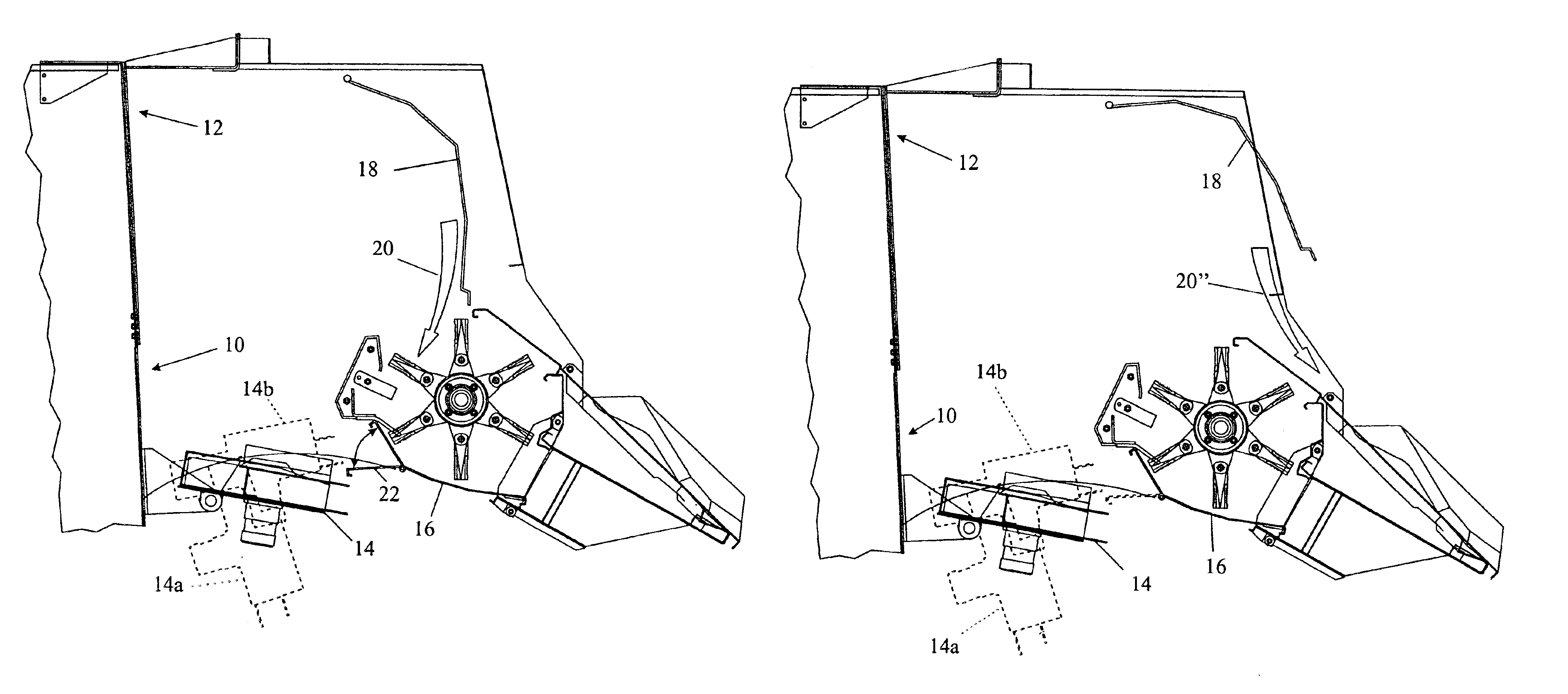
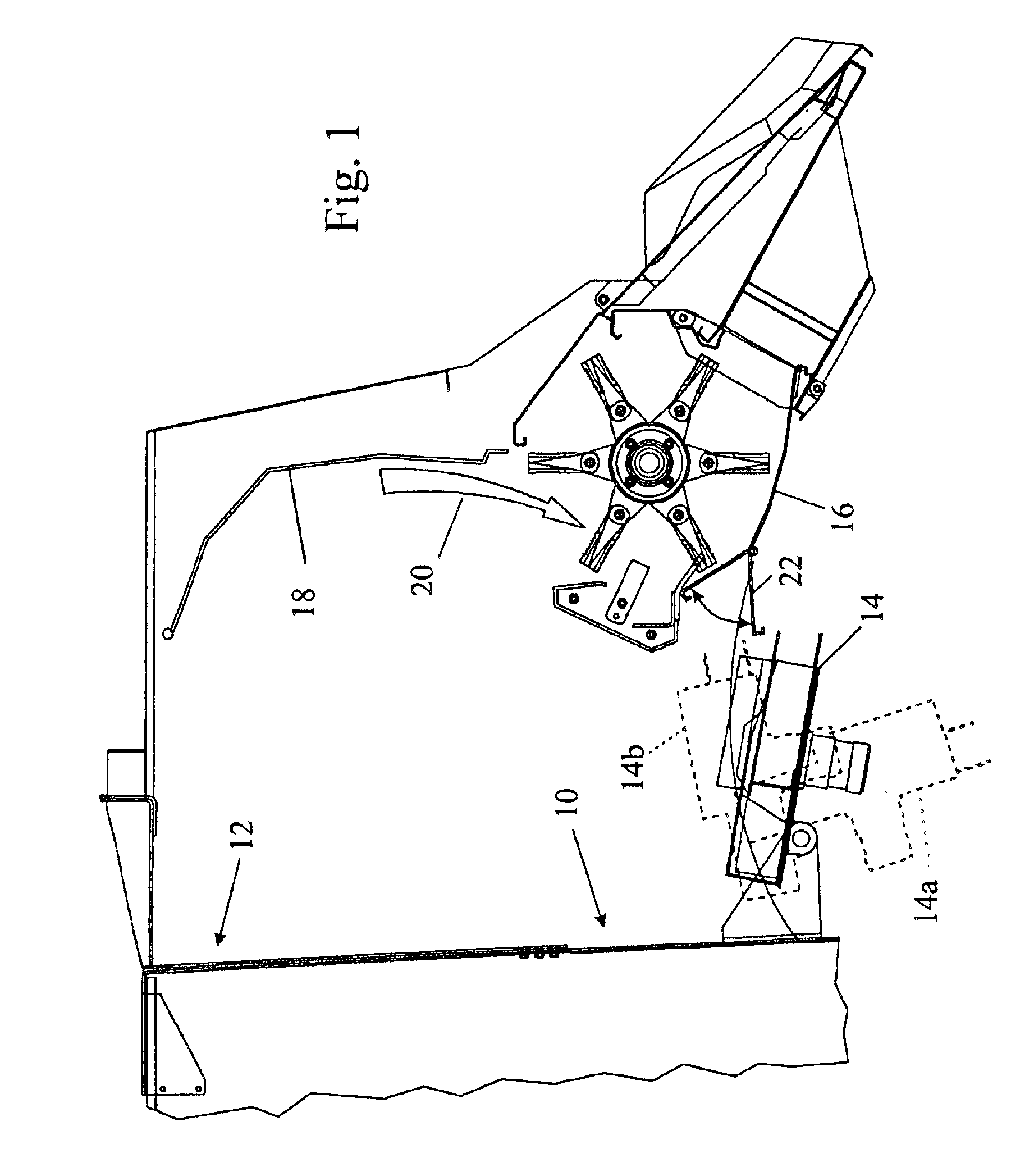
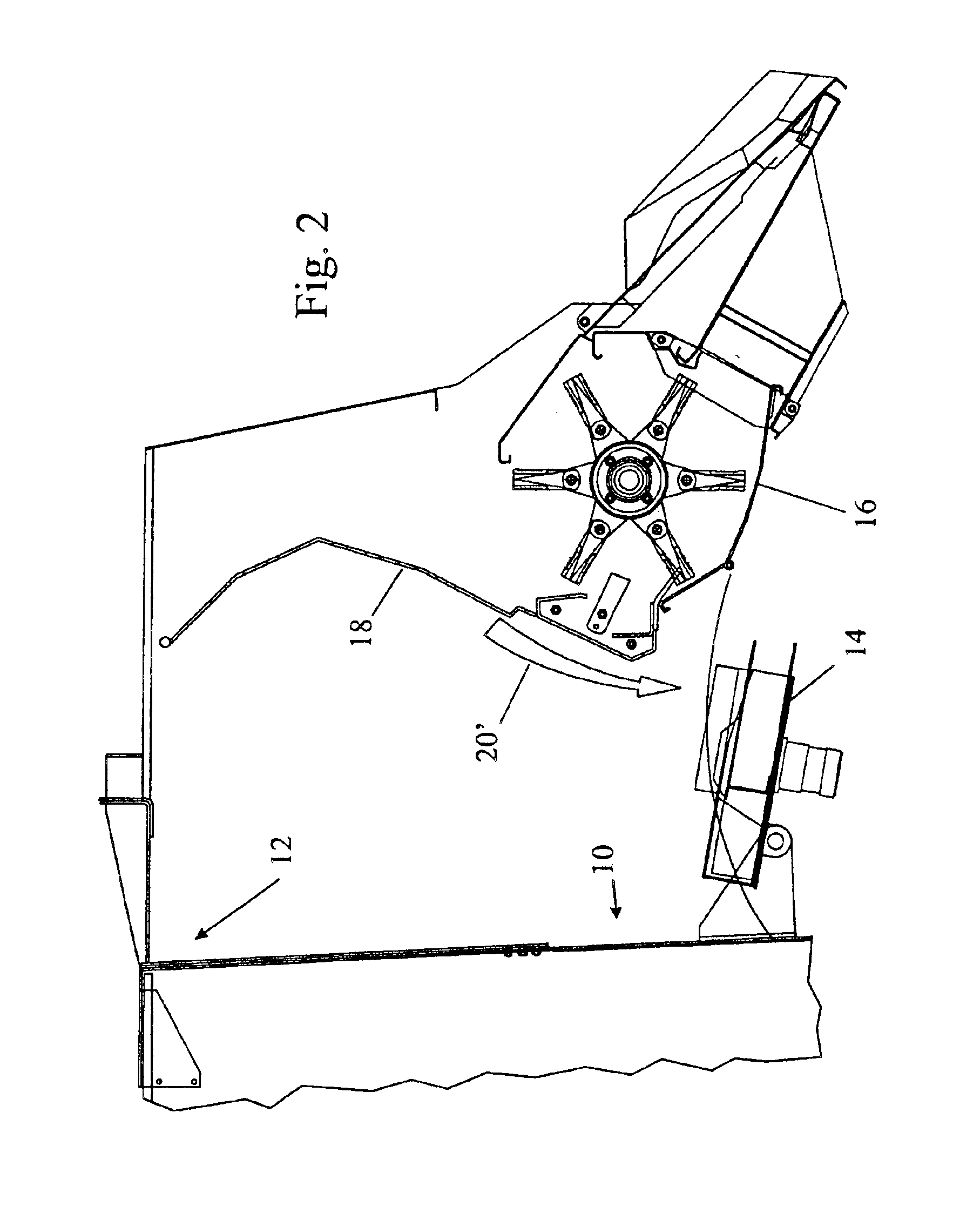
Combine harvesters are of course generally well known per se and one need not therefore be described herein in any great detail. Instead reference may be made for example to the above mentioned WO01 / 01754 which shows a combine harvester in its first figure and the second figure of which corresponds to the parts of the combine harvester shown in the accompanying drawings. It suffices for the purposes of the present invention to know that the various threshers, beaters, shakers and sieves within the combine harvester separate the grain, the chaff and the crop residue from one another. The chaff and the crop residue are discharged separately from the rear end of the combine harvester, the chaff discharge opening being designated 10 in the accompanying drawings and being disposed beneath the crop residue discharge opening 12.

A discharge device 14 is mounted below the chaff discharge opening 10. The discharge device 14 is constructed as a spreader which can be used to spread either the c...


PUM


Abstract

A combine harvester has at its rear end a crop residue chopper and a deflector plate for defining the path followed by the crop residue discharged from the rear end of the combine harvester. The deflector plate has a first position to direct the crop residue into the chopper and a second position to direct the crop residue forward of the chopper. In the invention, the deflector plate also has a third position in which the crop residue is directed to flow over the top and to the rear of the chopper.

Description

CROSS REFERENCE TO RELATED PATENT APPLICATIONSPriority is hereby claimed under 35 U.S.C. 119 to Great Britain Patent Application GB 0305253.7, titled “Combine Harvester”, filed Mar. 7, 2003, and having Jose Gryspeerdt and Edward H. Priepke as inventors.BACKGROUND OF THE INVENTIONThe present invention relates to a combine harvester.After a crop has been cut from a field by a combine harvester, it is processed by a threshing mechanism, beaters, shakers and a sieve unit to separate the grain from the remainder, which is made up of crop residue and chaff. The type of crop residue will depend on the nature of the crop being harvested, and the term is used herein to include such larger items as straw, stalks, corn cobs and other thick plant parts. The chaff on the other hand is much finer and includes such items as husks.It is well known, for example from WO01 / 01754, for the crop residue and the chaff to be discharged separately from the rear of the combine harvester and to be processed d...

Claims


Application Information

Patent Timeline
IPC IPC(8): A01D41/00A01D41/12A01F12/40
CPCA01F12/40A01D41/1243
Inventor GRYSPEERDT, JOSEPRIEPKE, EDWARD H.
Owner BLUE LEAF I P
Learn More