
Organic electroluminescent device and method of fabricating the same

a technology of electroluminescent devices and electroluminescent displays, which is applied in the direction of discharge tubes/lamp details, discharge tubes luminescent screens, electric discharge lamps, etc., can solve the problems of high power consumption, low luminescent insufficient luminescent efficiency of fluorescent materials, etc., to achieve low luminescent efficiency, low power consumption, and wide area

Inactive Publication Date: 2006-10-31
LG DISPLAY CO LTD
View PDF10 Cites 32 Cited by
  • Summary
  • Abstract
  • Description
  • Claims
  • Application Information

AI Technical Summary

Benefits of technology

[0014]An object of the present invention is to provide a fall color organic electroluminescent display using a phosphorescent material for at least one color of low luminescent efficiency and a fluorescent material for the other colors.
[0015]Another object of the present invention is provide a method of fabricating a full color organic electroluminescent display using a phosphorescent material for at least one color of low luminescent efficiency and a fluorescent material for the other colors.
[0016]Another object of the present invention is to provide a full color organic electroluminescent display of wide area having low power consumption.
[0017]Another object of the present invention is to provide a method of fabricating a full color organic electroluminescent display of wide area having low power consumption.

Problems solved by technology

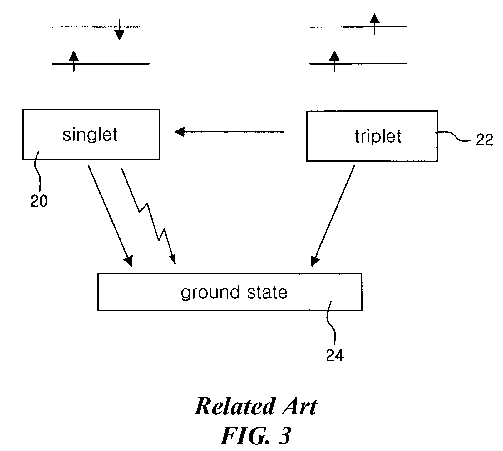
However, the fluorescent material EML does not have sufficient luminescent efficiency.
Specifically, since organic materials for R, G and B have different luminescent efficiencies, the EML of one color has lower luminescent efficiency than the EML of the other colors when driven with same current.
However, due to a high driving current, high power consumption is problematic.

Method used


Image

  • Organic electroluminescent device and method of fabricating the same
  • Organic electroluminescent device and method of fabricating the same
  • Organic electroluminescent device and method of fabricating the same

Examples


Embodiment Construction

[0035]Reference will now be made in detail to the preferred embodiments of the present invention, examples of which are illustrated in the accompanying drawings. Wherever possible, the same reference numbers will be used throughout the drawings to refer to the same or like parts.

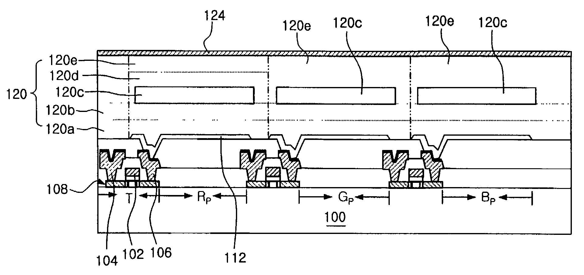
[0036]FIG. 4 is a cross-sectional view of an exemplary ELD according to the present invention. In FIG. 4, a driving device “T” may be formed on a substrate 100 including a pixel region (not shown). The pixel region may include a plurality of sub-pixel regions RP for red (R), GP for green (G), and BP for blue (B). The driving device “T” may drive a first electrode 112 in response to a signal received from a switching device (not shown) adjacent to the plurality of sub-pixel regions RP, GP, and BP. A thin film transistor (TFT) including a gate electrode 102, an active layer 108, and source and drain electrodes 104 and 106 may be used as the driving device “T” and the switching device (not shown). A storage cap...


PUM


Abstract

An organic electroluminescent display device includes a substrate having a plurality of sub-pixel regions for red, green and blue, a driving device on the substrate, a first electrode connected to the driving device, a hole being injected from the first electrode, a second electrode over the first electrode, an electron being injected from the second electrode, and a light emitting material layer interposed between the first and second electrodes, the light emitting material layer of at least one of the plurality of sub-pixel regions includes a phosphorescent material.

Description

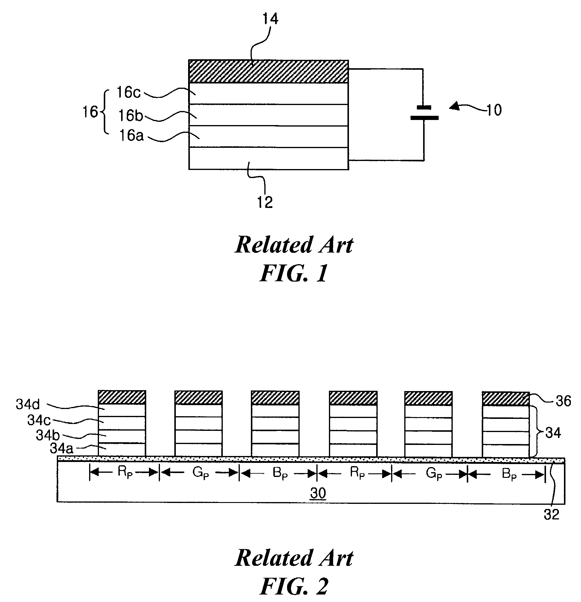
[0001]The present invention claims the benefit of the Korean Patent Application No. P2001-52309 filed in Korea on Aug. 29, 2001, which is hereby incorporated by reference.BACKGROUND OF THE INVENTION[0002]1. Field of the Invention[0003]The present invention relates to an organic electroluminescent display (ELD), and more particularly, to an organic ELD with high color purity with low driving current.[0004]2. Discussion of the Related Art[0005]Generally, organic ELD's use organic materials having high fluorescent or phosphorescent efficiency. Accordingly, band gaps of the organic materials may be easily developed through molecule design and synthesis. Moreover, organic ELDs can be fabricated on glass and plastic substrates because of their low fabricating temperatures.[0006]FIG. 1 is a cross-sectional view of an organic ELD according to the related art. In FIG. 1, an organic ELD 10 includes a first electrode 12, a second electrode 14, and an organic layer 16 interposed therebetween. E...

Claims


Application Information

Patent Timeline
Patent Type & Authority Patents(United States)
IPC IPC(8): H05B33/00H05B33/14H01L27/32H01L51/50H05B33/10H05B33/12H05B33/26H05B33/28
CPCH01L27/3211H01L27/3244H01L51/5016H01L51/5096H10K59/35H10K59/12H10K50/11H10K2101/10H10K50/18H05B33/14
Inventor PARK, JAE-YONGYOO, CHOONG-KEUNPANG, HEE-SUK
Owner LG DISPLAY CO LTD
Learn More