
Work vehicle having engine and belt-type continuously variable transmission device

a technology of transmission device and engine, which is applied in the direction of mechanical equipment, transportation and packaging, and jet propulsion mounting, etc., can solve the problems of reducing the cooling performance, lowering the cooling performance, and reducing the cooling air led to the surface of the muffler, so as to achieve efficient muffler temperature rise, efficient cooling, and efficient hitting

Active Publication Date: 2013-05-14
KUBOTA CORP
View PDF7 Cites 29 Cited by
  • Summary
  • Abstract
  • Description
  • Claims
  • Application Information

AI Technical Summary

Benefits of technology

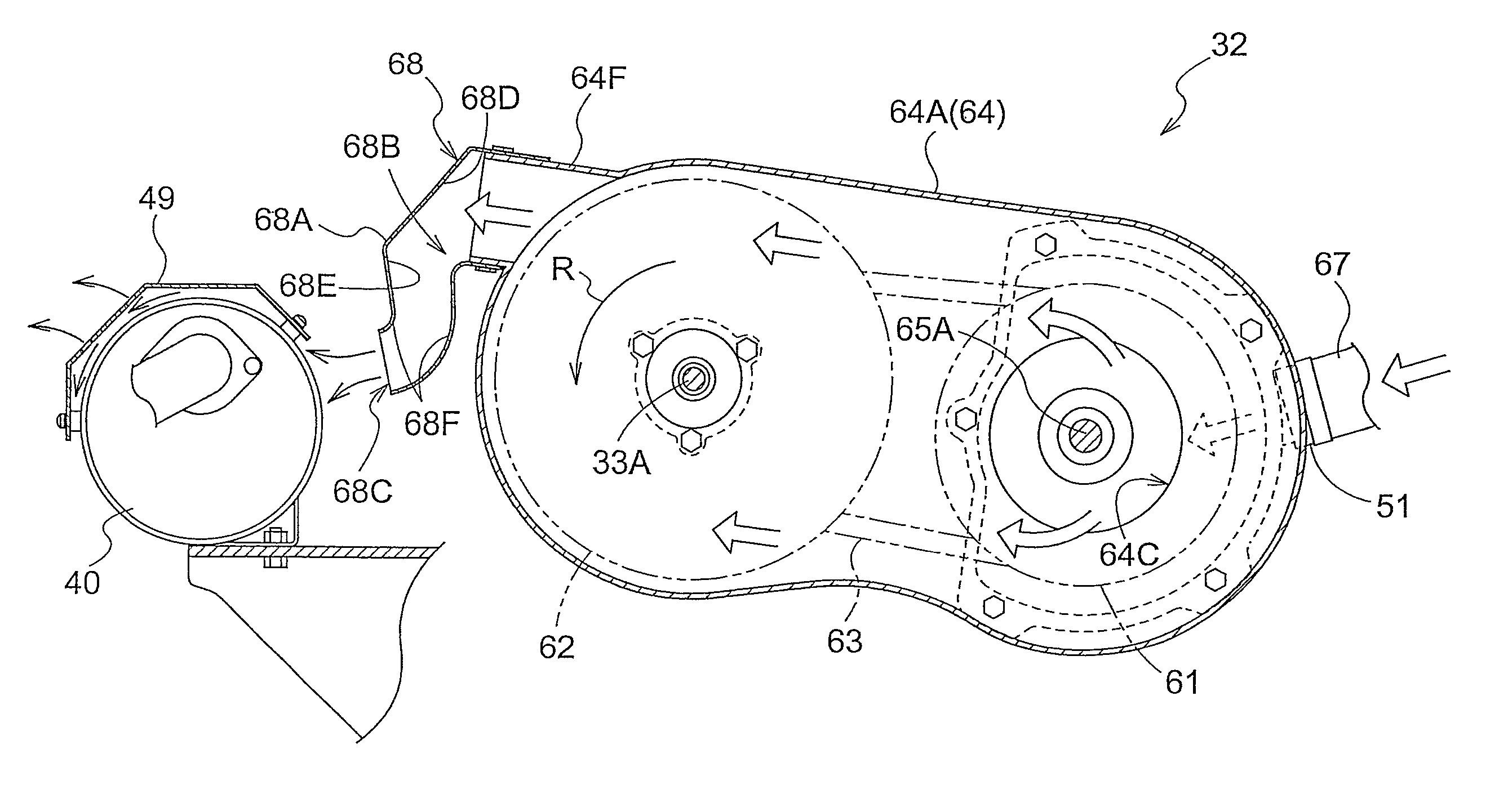
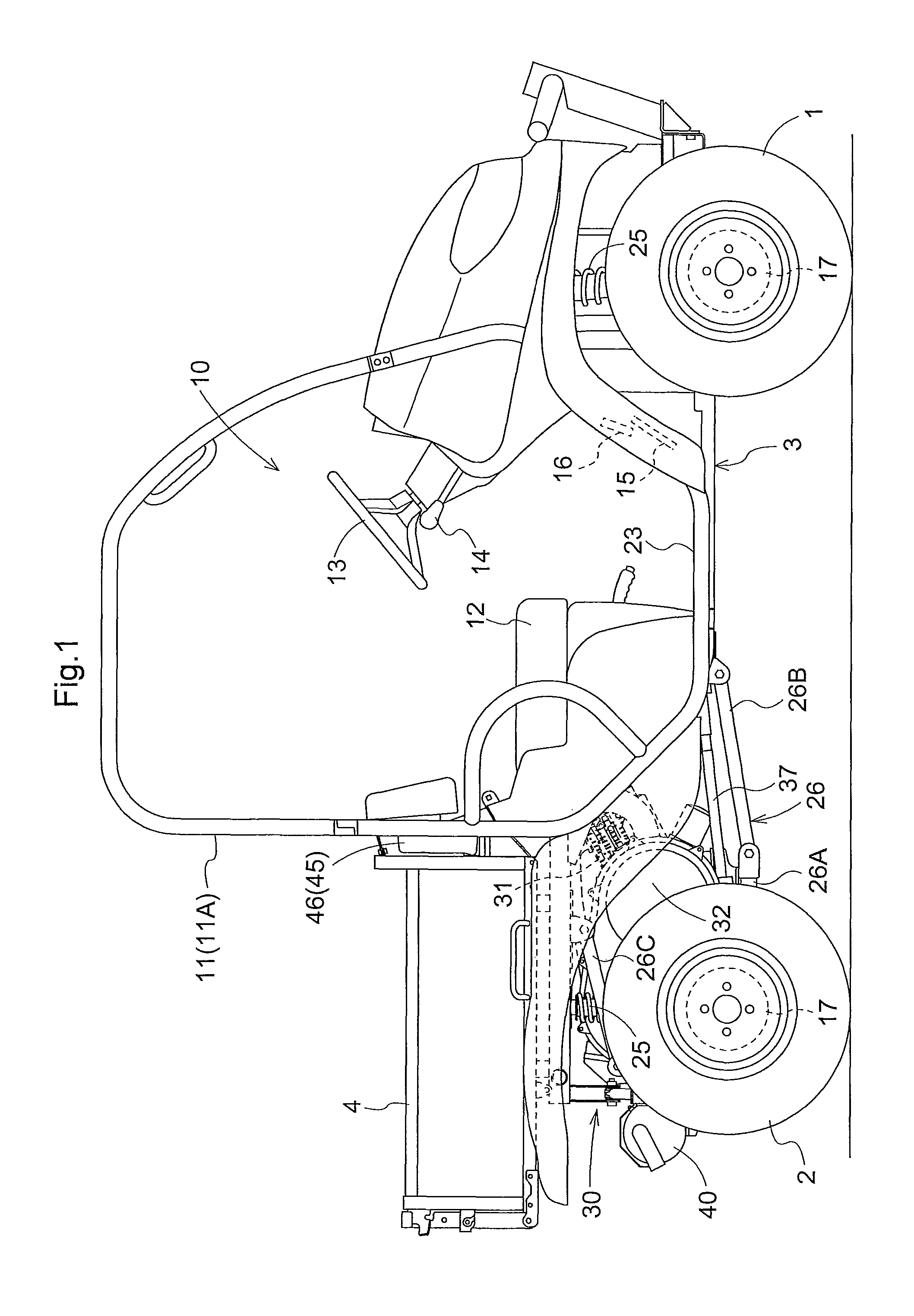
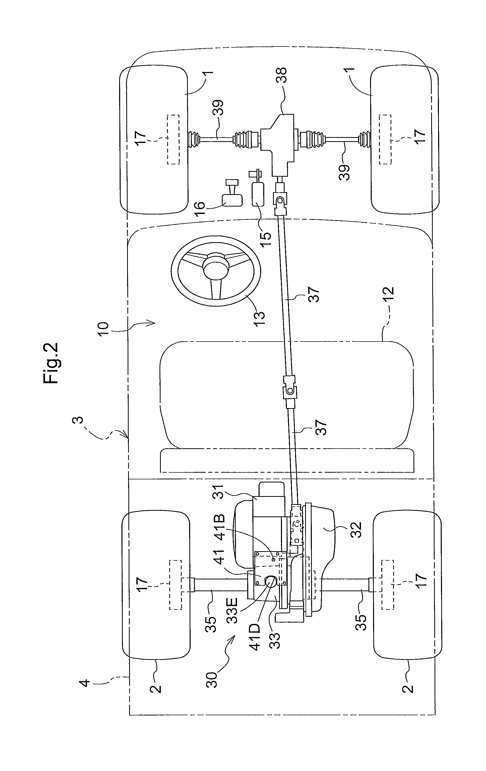
[0010]According to this configuration, the cooling air which has been used for cooling an inside of the CVT case is discharged from the discharge part of the CVT case through the exhaust duct to a rear side of the vehicle body, and blown to the muffler in a direction orthogonal to an extending direction of the muffler (longitudinal direction of the muffler). In other words, the cooling air hits directly into the muffler. Accordingly, when the vehicle body is running, the cooling air discharged from the discharge part reaches the surface of the muffler without being influenced by the air flow from outside, and thus the cooling of the muffler is achieved. In addition, since a cross section of the exhaust opening for exhausting the cooling air is formed so as to correspond to the muffler in the extending direction, a hitting degree on the muffler by the cooling air is high, and the hitting is efficient. As a result, temperature raise of the muffler is effectively suppressed by utilizing the cooling air which has been used for cooling the belt-type CVT.
[0011]It is convenient when a heat shield plate is arranged along an outer face of the muffler at a distance, and the cooling air discharged from the exhaust duct is supplied to a space between the muffler and the heat shield plate. With this configuration, by supplying the cooling air from the exhaust duct to the space between the outer face of the muffler and the heat shield plate, the cooling is realized in which the cooling air is continuously brought into contact with the outer face of the muffler. In other words, as compared with a local cooling in which the cooling air is simply blown to an object, a wider area of the outer face of the muffler can be efficiently cooled.
[0012]By setting the cross-sectional horizontal length of the exhaust opening to approximately twice the cross-sectional horizontal length of the inflow opening, a wider area of the outer face of the muffler can be cooled.

Problems solved by technology

As a result, an amount of the cooling air led to a surface of the muffler is reduced, and thus cooling performance is lowered.
However, even though the lowering in the cooling performance by the air flow from outside during the vehicle body running is suppressed, the cooling itself is not so efficient.

Method used


Image

  • Work vehicle having engine and belt-type continuously variable transmission device
  • Work vehicle having engine and belt-type continuously variable transmission device
  • Work vehicle having engine and belt-type continuously variable transmission device

Examples


embodiment

Effect of Embodiment

[0074]As described above, according to the present invention, the cooling air supplied to the CVT case 64 is brought into contact with the driving pulley 61, the driven pulley 62, and the endless belt 63, to thereby cool them. In addition, since the cooling air is supplied from the case main body 64A of the CVT case 64 and the cooling air is discharged from the discharge part 64F of the case main body 64A, even during an operation of removing the cover member 64B, it is not necessary to remove a duct for supplying the cooling air, a duct for exhausting the cooling air and the like, and thus the operation is facilitated.

[0075]In the case main body 64A, the bulging part 64D bulging in a side opposite to the cover member 64B (the transmission case 33 side) is formed, and the discharge part 64F is formed in the bulging part 64D. In the discharge part 64F, along with the rotation of the driven pulley 62, the wind pressure acting in a tangential direction from the uppe...


PUM


Abstract

A work vehicle includes: a muffler which flows exhaust from an engine and extends in a transverse direction so as to allow the exhaust from the engine to flow in the transverse direction; and a CVT case for covering a belt-type CVT positioned frontward of the muffler in a longitudinal direction. The CVT case includes a cooling structure for introducing cooling air from outside, cooling the belt-type CVT, and discharging the cooling air from a discharge part. An exhaust duct includes an inflow opening to be connected to the discharge part for allowing the cooling air to flow into the exhaust duct, and an exhaust opening for allowing the cooling air to flow out rearward. The exhaust opening is elongated in an extending direction of the muffler and oriented in a direction that allows the cooling air flowing out to hit the muffler.

Description

BACKGROUND[0001]1. Field of the Invention[0002]The present invention relates to a cooling technique of a belt-type continuously variable transmission device (CVT) and a muffler in a work vehicle having an engine and the belt-type CVT.[0003]2. Description of the Related Art[0004]With respect to the cooling technique of the belt-type CVT, Japanese Unexamined Patent Application Publication No. 2005-238988 describes a vehicle in which a body frame is provided with an engine, a belt-type CVT for changing a driving force of the engine, and a muffler connected to an exhaust pipe of the engine. In this patent document, the belt-type CVT has a transmission cooling system for sucking external cooling air from a feed duct; supplying the cooling air into a belt case to thereby cool the belt-type CVT; and sending this cooling air from the belt case through an exhaust duct to a rear part of a vehicle body. The exhaust duct and the muffler are arranged in parallel with each other in a lateral dire...

Claims


Application Information

Patent Timeline
Patent Type & Authority Patents(United States)
IPC IPC(8): B60K11/06
CPCB60K5/04B60K11/06B60K13/04B60K17/08F16H57/0489F16H57/0416B60K17/344B60Y2200/141B60Y2200/22
Inventor BESSHO, HIROKIIMANISHI, RYOUZOUKAWAMURA, SHOICHIROMURAKAWA, MASATAKE
Owner KUBOTA CORP
Learn More