Broadband antennas
Inactive Publication Date: 2005-02-22
UNITED STATES OF AMERICA
View PDF13 Cites 36 Cited by
Summary
Abstract
Description
Claims
Application Information
AI Technical Summary
This helps you quickly interpret patents by identifying the three key elements:
Problems solved by technology
Method used
Benefits of technology
Benefits of technology
The present invention is a variable length antenna that may be switched to provide the equivalent function of a broadband antenna. It is an apparatus and method for quasi-continuously transmitting or receiving signals at a plurality of frequencies by changing the effective length of the antenna using a variety of switching mechanisms. The antenna of the present invention may comprise a plurality of antenna segments, a plurality of selectively actuable switches for interconnecting the antenna segments, and a switching mechanism operably coupled to the plurality of selectively actuable switches for switching them at a switching rate that is greater than twice the highest frequency to be transmitted or received. This rate will be fast enough to allow the antenna to sample the highest frequency and all of the required lower frequencies within the desired frequency range without the loss of information at any frequency. The switching rate is slow enough, however, to allow sampling of the frequency at each antenna length before the next antenna length is activated.
In accordance with the present invention, transmitting or receiving signals at a plurality of frequencies may be accomplished by employing conductive fluid to change the effective length of the antenna. The antenna may comprise a plurality of antenna segments, each of which comprises a dielectric container for holding a conductive fluid. In this embodiment, the antenna may further comprise a reservoir connected to the antenna segments and a pressure regulatorsystem for controlling the pressure in the antenna segments. As the pressure in the antenna segments changes, the effective length of the antenna changes. This allows the antenna to be tuned to both harmonically related and non-harmonically related frequencies.
An important advantage of this invention is that it provides a broadband antenna using a single variable length antenna, thus simplifying the construction of antenna arrays. This feature is important because RF communications systems may employ one antenna embodying various features of the present invention instead of multiple antennas, which would otherwise be necessary to cover the same bandwidth. This antenna is expected to find wide applications in communications applications, particularly on board ships and airplanes.
Problems solved by technology
Under these circumstances, using multiple antennas or larger broadband antennas is not practical.
The disadvantage of this system, however, is that the antenna effectively samples only one frequency at a time.
Method used
Image
Click on the blue label to locate the original text in one second.
Reading with bidirectional positioning of images and text.
Examples
first embodiment
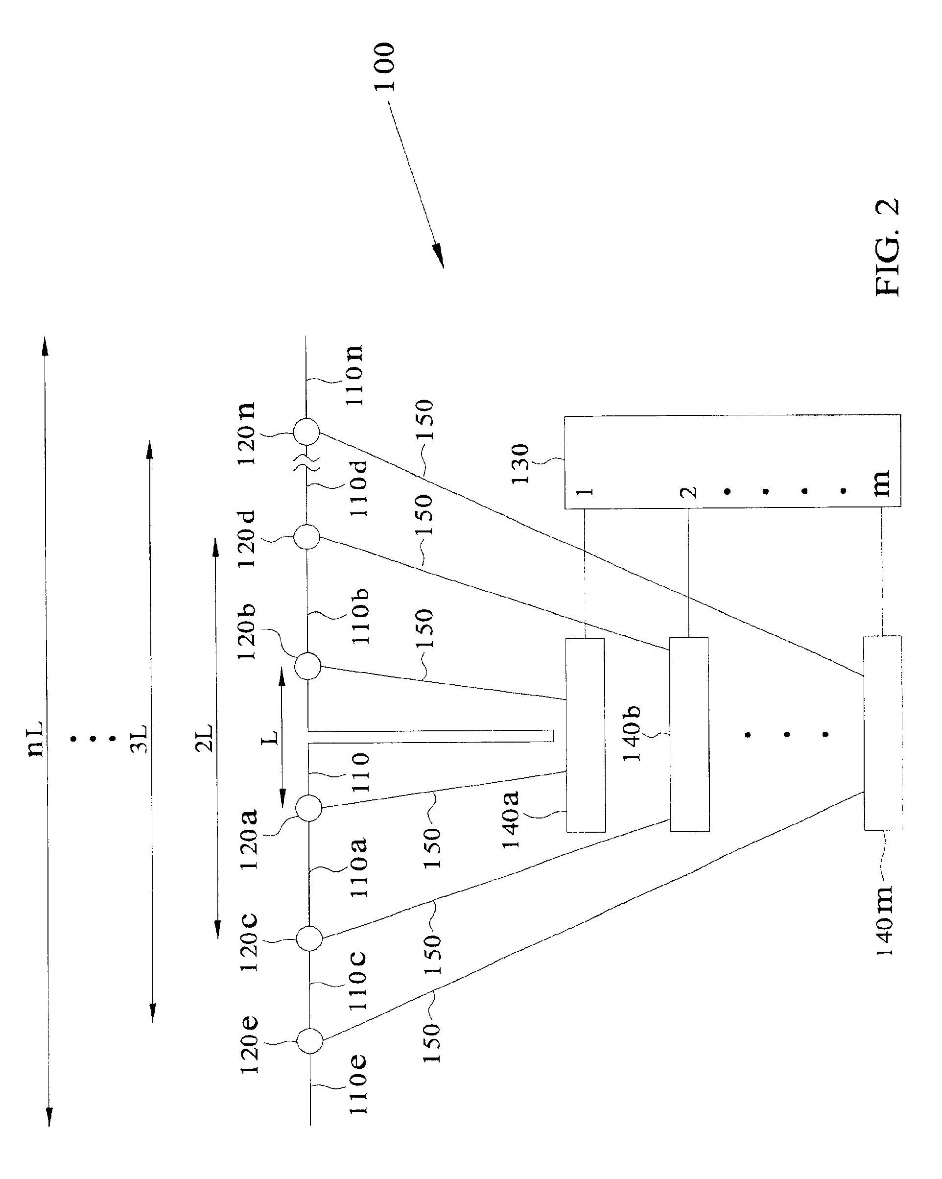
FIG. 2 shows a variable length antenna for transmitting or receiving at a plurality of frequencies in accordance with the present invention. In this embodiment, variable length antenna 100 comprises a plurality of antenna segments 110, 110a, 110b, 110c, 110d, 110e, . . . , 110n, a plurality of selectively actuable switches 120a, 120b, 120c, 120d, 120e, . . . , 120n, a switch controller 130, and a plurality of light sources 140a, 140b, . . . , 140m. As contemplated in this embodiment, light sources 140a, 140b, . . . , 140m, such as lasers, pulsed lasers, light emitting diodes (LEDs), and diode lasers, are operably coupled to switches 120a, 120b, 120c, 120d, 120e, . . . , 120n via optical fibers 150. However, other means, such as optical waveguides, optical switches, light valves, and optical MEMs devices, may also be used to couple light sources 140a, 140b, . . . , 140m to switches 120a, 120b, 120c, 120d, 120e, 120n. Switch controller 130 selects light sources 140a, 140b, . . . , 140...
second embodiment
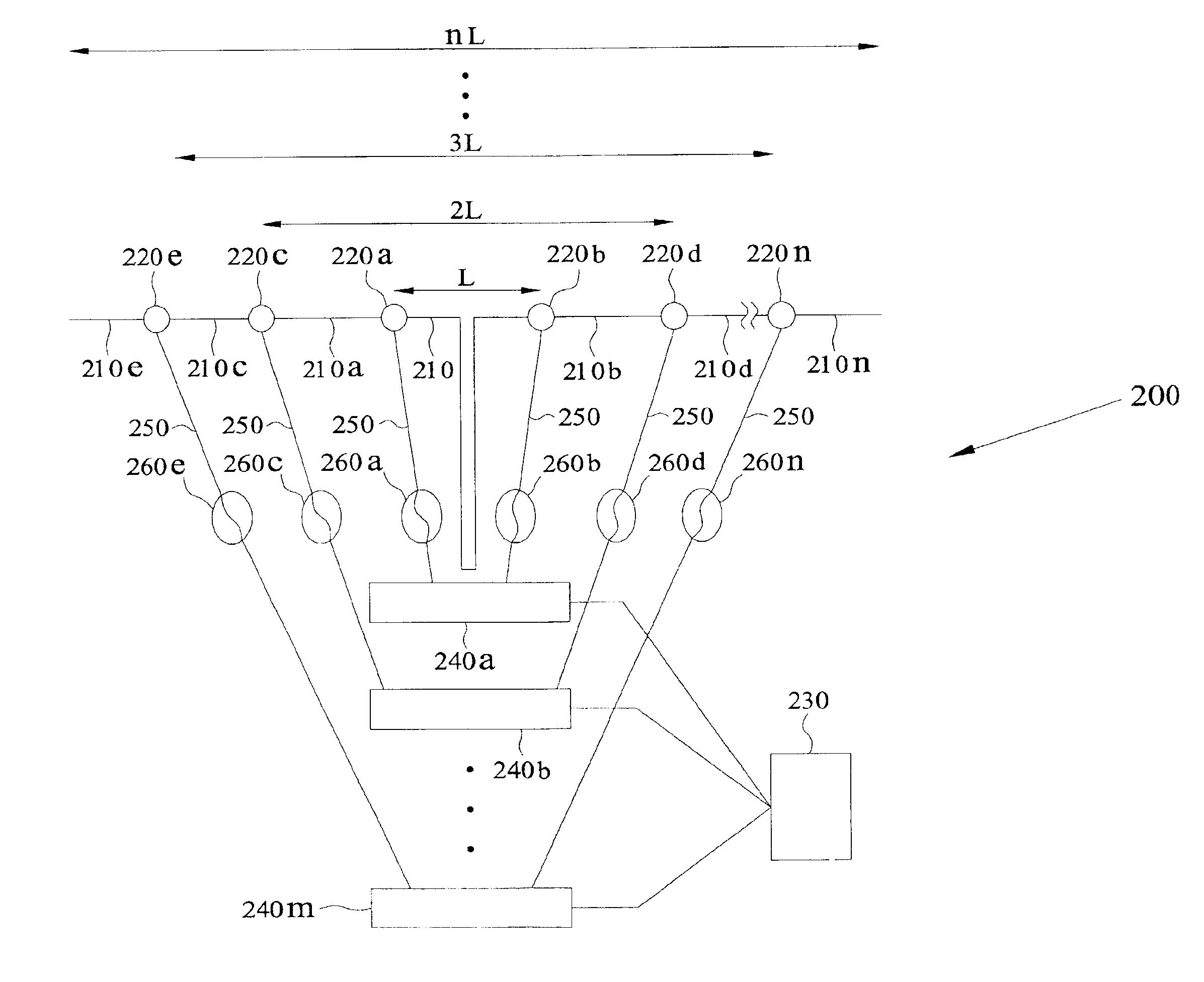
a variable length antenna for transmitting or receiving at a plurality of frequencies in accordance with the present invention is shown in FIG. 3. In this embodiment, variable length antenna 200 comprises a plurality of antenna segments 210, 210a, 210b, 210c, 210d, 210e, . . . , 210n, a plurality of selectively actuable switches 220a, 220b, 220c, 220d, 220e, 220n, a switching device 230, and a plurality of light sources 240a, 240b, . . . , 240m. Optical fibers 250 operably couple light sources 240a, 240b, . . . , 240m to actuable switches 220a, 220b, 220c, 220d, 220e, . . . , 220n. As with the first embodiment, other means of operably coupling light sources 240a, 240b, . . . , 240m to actuable switches 220a, 220b, 220c, 220d, 220e, . . . , 220n may be used, including optical waveguides, optical switches, light valves, and optical MEMs devices. In this embodiment, switching device 230 simultaneously switches light sources 240a, 240b, . . . , 240m from a non-emissive to an emissive st...
PUM
Abstract
The fast switching multifunction antenna of the present invention is a variable length antenna that may be switched to provide the equivalent function of a broadband antenna. The variable length antenna quasi-continuously transmits or receives signals at a plurality of frequencies by changing the effective length of the antenna using a variety of switching mechanisms. The present invention may comprise a plurality of antenna segments, a plurality of selectively actuable switches for interconnecting the antenna segments, and a switching mechanism operably coupled to the plurality of selectively actuable switches for switching them at a switching rate that is greater than twice the highest frequency to be transmitted or received. The switching rate will be fast enough to allow the antenna to sample the highest frequency and all of the required lower frequencies within the desired frequency range without the loss of information at any frequency. However, the switching rate is slow enough to allow sampling of the frequency at each antenna length before the next antenna length is activated.
Description
DOCUMENTS INCORPORATED BY REFERENCEThe following documents are hereby incorporated by reference into this specification: Rogers, Dennis L., “Monolithic Integration of a 3-GHz Detector / Preamplifier Using a Refractory-Gate, Ion-Implanted MESFET Process”, IEEE Electron Device Letters, 1996, EDL-7, pp. 600-602; Albares, D. J., Garcia, G. A., Chang, C. T., and Reedy, R. E., “Optoelectronic Time Division Multiplexing”, Electronic Letters, 1987, 23, pp. 327-328; and Mendel'son, V. L., Kozlov, A. I., and Finkel'shteyn, M. I., “Some Electrodynamic Models of Ice Sheets, Useful in Radar-Sounding Problems”, Izvestiya Akademii Nauk SSR, Fizika Atmosfery I Okanea, 1972, 8, pp. 396-402 [translated in Izvestiya Academy of Sciences USSR, Atmospheric and Oceanic Physics, 1972, pp 225-229].BACKGROUND OF THE INVENTIONNumerous scientific, civilian, and military applications require both narrowband and broadband communications. In typical applications, space and / or weight are at a premium and multiple fr...
Claims
Application Information
Patent Timeline
Application Date:The date an application was filed.
Publication Date:The date a patent or application was officially published.
First Publication Date:The earliest publication date of a patent with the same application number.
Issue Date:Publication date of the patent grant document.
PCT Entry Date:The Entry date of PCT National Phase.
Estimated Expiry Date:The statutory expiry date of a patent right according to the Patent Law, and it is the longest term of protection that the patent right can achieve without the termination of the patent right due to other reasons(Term extension factor has been taken into account ).
Invalid Date:Actual expiry date is based on effective date or publication date of legal transaction data of invalid patent.
