
Input power limiter for a microwave receiver

a technology for limiting power and microwave receivers, applied in the field of high frequency, can solve the problems of high cost and significant space, high resolution, and inapplicability of epitaxial silicon pin diodes

Inactive Publication Date: 2005-02-08
APPLE INC
View PDF1 Cites 12 Cited by
  • Summary
  • Abstract
  • Description
  • Claims
  • Application Information

AI Technical Summary

Benefits of technology

According to one aspect of this invention there is provided a power limiter comprising input terminals and a transmission line arranged to couple a high frequency signal supplied to the input terminals to an output of the limiter, the transmission line comprising a plurality of successive transmission l...

Problems solved by technology

Consequently, such a microwave power limiter can be very effective, but it involves disadvantages of a high cost and significant space, being assembled from discrete components typically using an epitaxial silicon semiconductor process, and loss can be introduced at the interface between the limiter and the LNA.
It would be desirable to integrate the microwave power limiter with the LNA, but this is not practical with epitaxial silicon PIN diodes.
However, this provides a lateral arrangement (rather than a vertical arrangement as in the epitaxial silicon PIN diode) which has the disadvantages of requiring close spacing of the implanted regions, and hence a high resolution, and leakage of carriers from the intrinsic semiconductor between the implanted regions into the remainder of the substrate.
Further, the implanted P-type region in this case uses zinc, which creates other problems for combined fabrication processes for MESFETs and HBTs (heterojunction bipolar transistors).
The fast response of the Schottky diode makes it unsuitable as a replacement for a PIN diode in a microwave power limiter.
Such an arrangement is unsuitable for use at high frequencies, for example of 1 GHz or more, because the capacitance of the diodes in combination with the series resistance introduces a signal distortion and a loss which are not acceptable (as well as a delay which may be acceptable).

Method used


Image

  • Input power limiter for a microwave receiver
  • Input power limiter for a microwave receiver
  • Input power limiter for a microwave receiver

Examples


Embodiment Construction

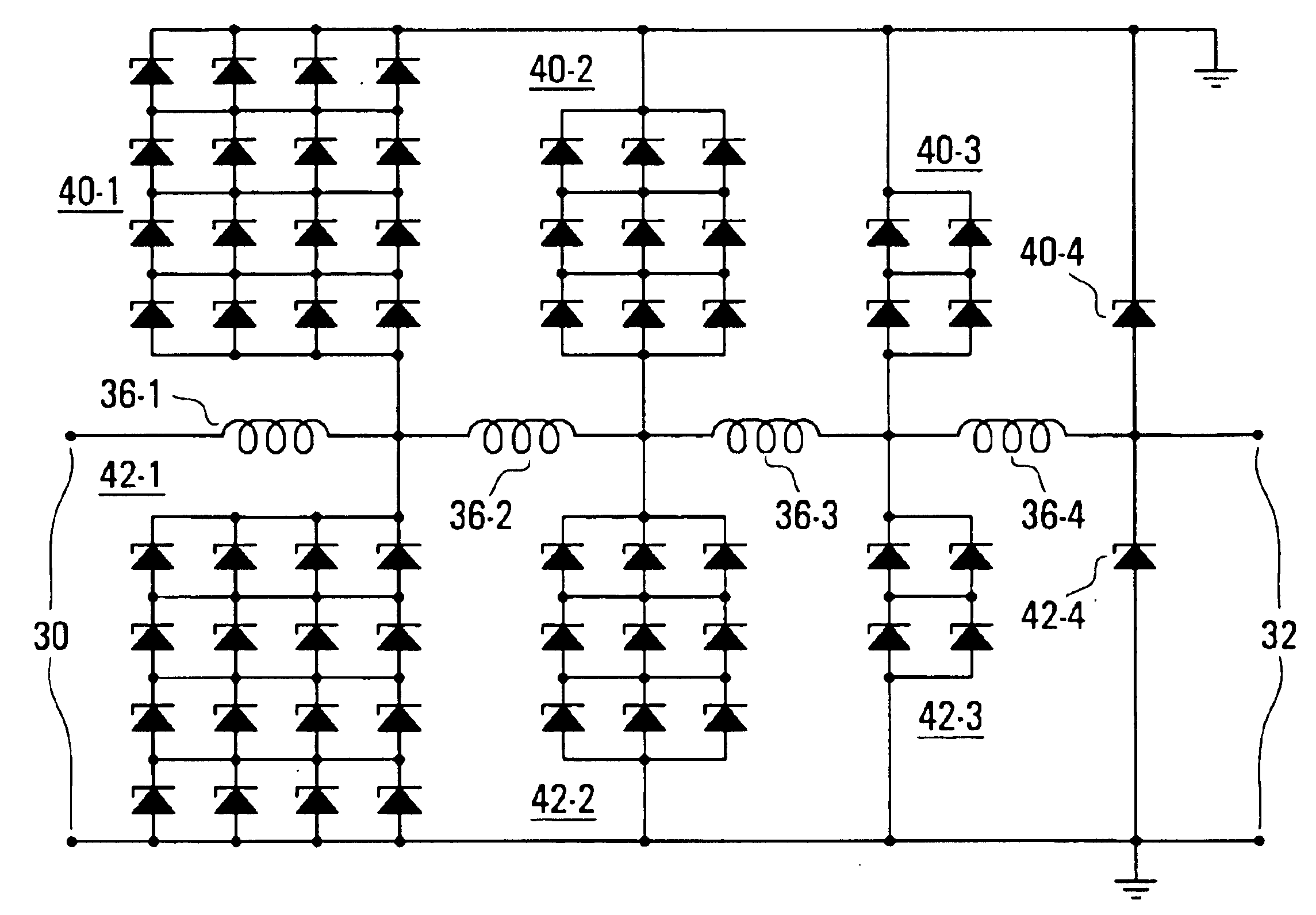
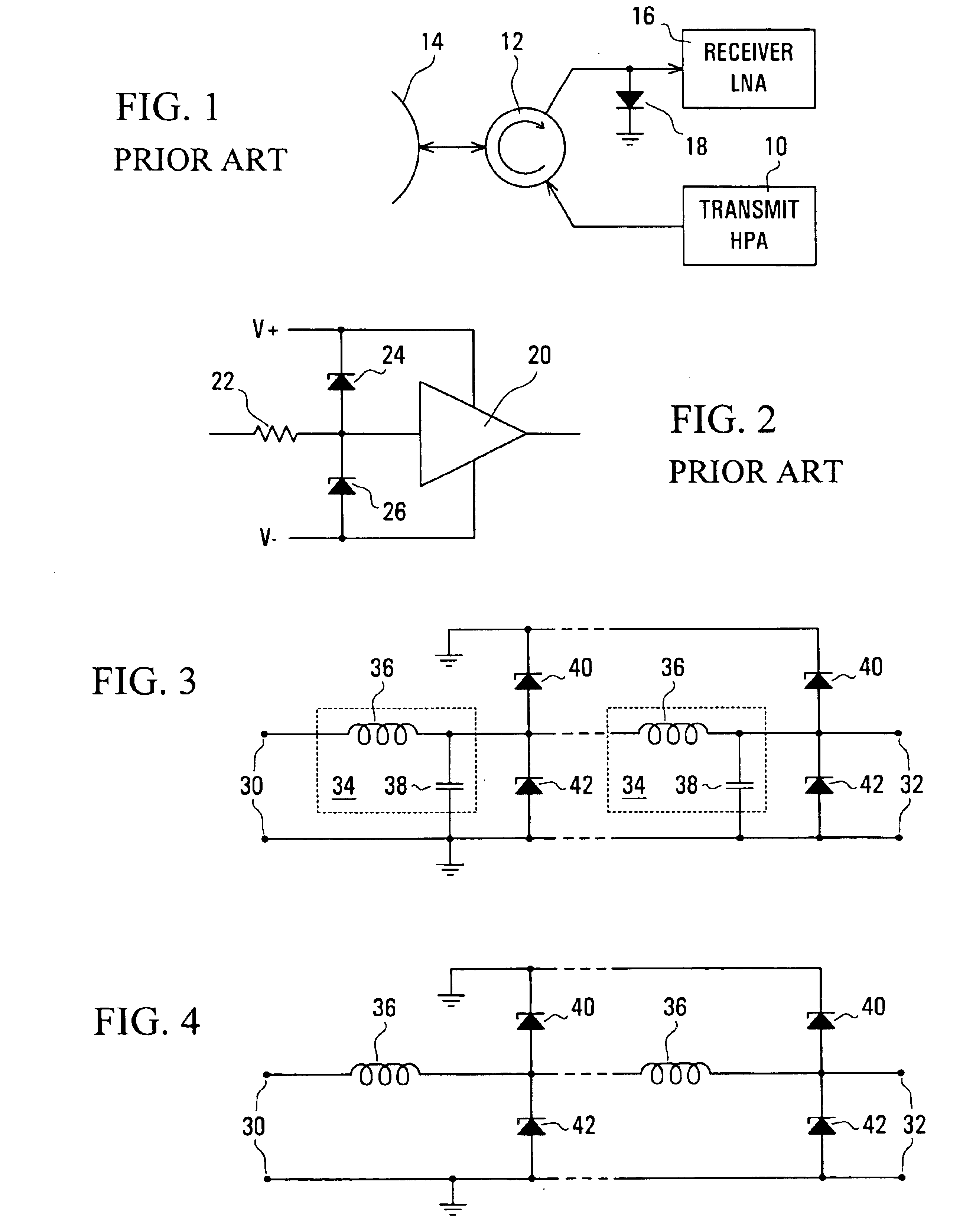
Referring to the drawings, FIG. 1 illustrates a microwave transmitter and receiver arrangement, for example for a radar system, in which an output of a transmit high power amplifier (HPA) 10 is coupled via a circulator 12 to an antenna 14. Signals received via the antenna 14 are coupled via the circulator 12 to an input of a receiver low noise amplifier (LNA) 16. In order to protect the LNA 16 from damage due to excessive power microwave signals and interference being supplied to its input, either by reflection by the antenna 14 of a signal from the HPA 10 or, especially, transmitted from some other transmitter, a microwave power limiter is connected at the input of the LNA 16.

As shown in the arrangement of FIG. 1, the microwave power limiter is constituted by a PIN diode 18 connected between the input of the LNA 16 and ground. As discussed above, such a microwave power limiter has the disadvantages of high cost, space requirements, and potential loss at its interface with the LNA 1...


PUM


Abstract

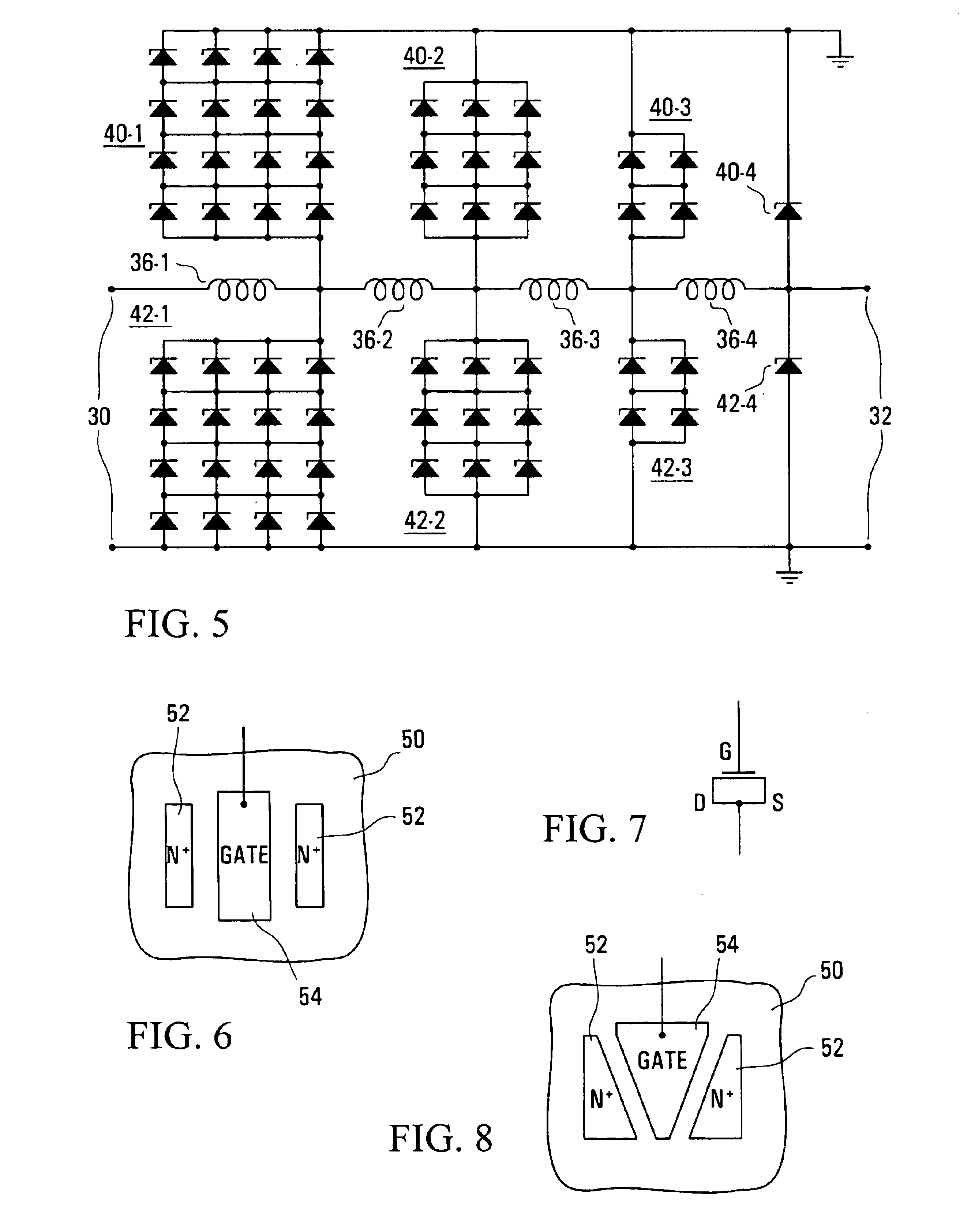
A power limiter for limiting power of high frequency signals at an input to a receiver comprises a plurality of transmission line sections connected in succession. Each section has a series inductance coupling an input to an output of the section, and a shunt capacitance constituted by capacitance of at least one pair of oppositely-poled Schottky diodes coupled at the output of the section to limit voltage of the signal at the output. Individual diodes can be replaced by series-connected diodes, or by an array of parallel and series-connected diodes, in different sections for improved performance of the limiter. The limiter can be integrated with a GaAs low noise amplifier of the receiver.

Description

FIELD OF THE INVENTIONThis invention relates to high frequency, for example microwave, input signal power limiters for limiting input signal and interference power to an input of a receiver, such as a radar receiver or a receiver of a wireless communications system.BACKGROUNDIt is well known to provide a low noise amplifier (LNA) at an input of a high frequency, e.g. microwave, receiver in order to amplify small signals which are desired to be received. It is also well known to provide, at an input to the LNA, a microwave power limiter which serves to limit the power of signals and interference which may be supplied to the LNA, in order to protect the LNA from damage which may otherwise be caused by an excessive input power.For example, in a radar system an output of a transmit high power amplifier (HPA) may be coupled via a circulator to an antenna, and the antenna may be coupled via the circulator and a microwave power limiter to the input of the receiver LNA. The microwave power ...

Claims


Application Information

Patent Timeline
IPC IPC(8): H03G11/00H03G11/02
CPCH03G11/02
Inventor BENNETT, JEFFREY H.CEN, YUANFEI
Owner APPLE INC
Learn More