Method and device for improving efficiency of frequency synthesizer

a frequency synthesizer and efficiency technology, applied in the direction of oscillation comparator circuits, pulse automatic control, digital transmission, etc., can solve the problems of increasing the settling time of the frequency synthesizer, etc., to reduce the number of cycle slips, and increase the variation range of the phase detector

Inactive Publication Date: 2005-02-08
NOKIA CORP
View PDF6 Cites 0 Cited by
  • Summary
  • Abstract
  • Description
  • Claims
  • Application Information

AI Technical Summary

Benefits of technology

[0010]A different method and a device have now been invented for reducing cycle slips and for increasing a variation range of a phase detector to exceed the commonly used ±2π. In the method, a linear range [−2 pi,+2 pi] of a phase comparator is formed by a first pair of flip-flops, such as a pair of d flip-flops, in the same manner as in the prior art publication U.S. Pat. No. 6,100,721. Additionally, in the method, a linear range [2 pi,4 pi] or [−4 pi,−2 pi] of the phase comparator is formed by a second pair of flip-flops after exceeding the phase difference 2 pi, unlike in said prior art publication, in which said second pair of flip-flops is used for changing a value of a counter. From the range [2 pi,4 pi] or [−4 pi,−2 pi], a normal state within the linear range [−2 pi,2 pi] is returned to as soon as the phase difference is back less than 2 pi. The method reduces the number of cycle slips and improves the performance of a transmitter-receiver device, such as mobile station, as the signal settling time of a frequency synthesizer becomes shorter.

Problems solved by technology

However, a narrow band delays the loop, which means an increase in the settling time in the frequency synthesizer.
However, a high comparision frequency may cause cycle slips, like those presented in FIG. 1c, in the signal settling, particularly in large frequency hops, which further increases the settling time of the frequency synthesizer.

Method used


Image

  • Method and device for improving efficiency of frequency synthesizer
  • Method and device for improving efficiency of frequency synthesizer
  • Method and device for improving efficiency of frequency synthesizer

Examples


Embodiment Construction

e detector;

[0023]FIGS. 3b and 3c shows an operating range of the phase detector of the invention;

[0024]FIG. 4 is a flow chart of the method of the invention;

[0025]FIG. 5 is a block diagram of a frequency synthesizer of the invention;

[0026]FIG. 6 is a block diagram of a communication device of the invention;

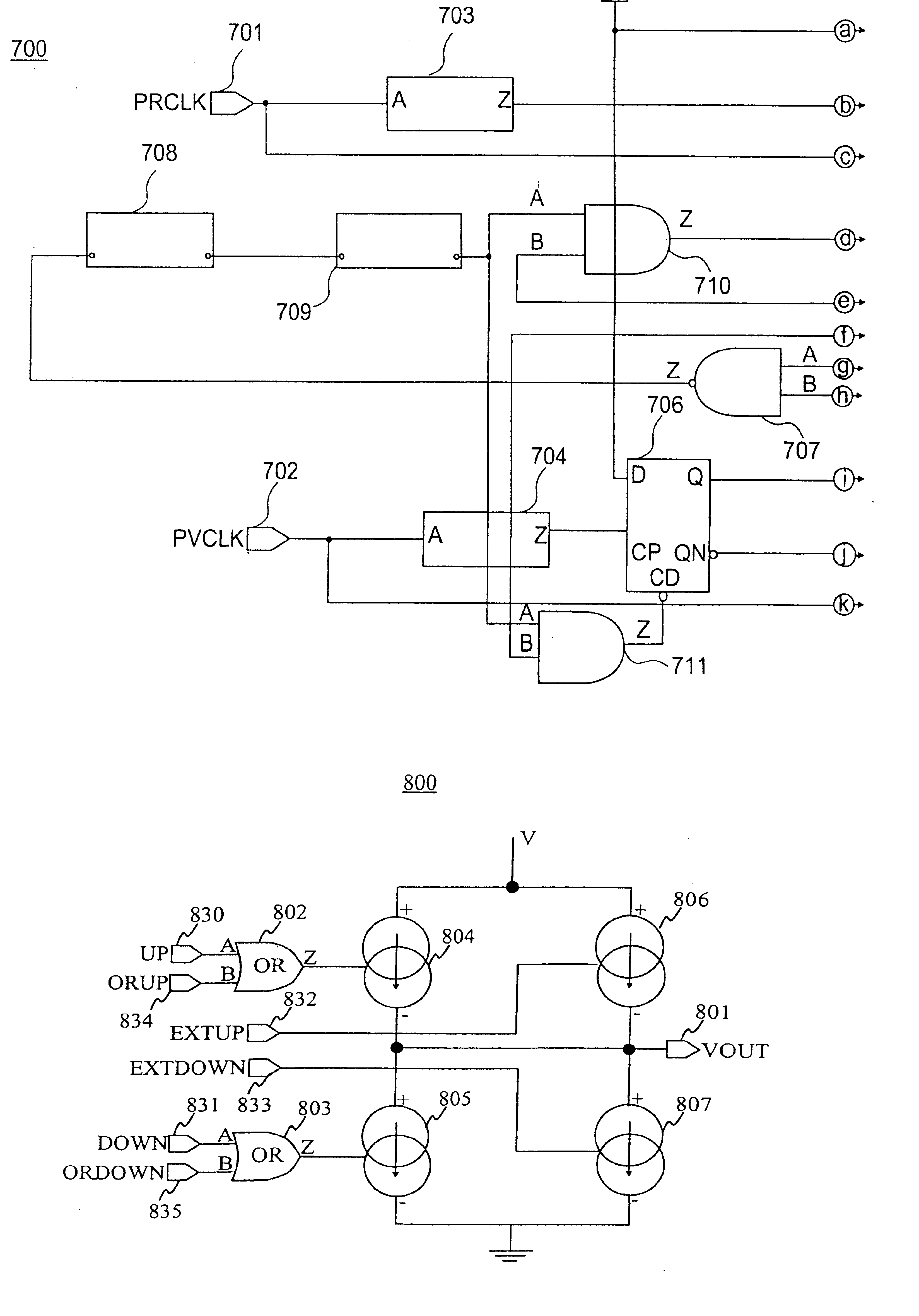
[0027]FIG. 7, shown in the drawing Figures as FIG. 7A, FIG. 7B and FIG. 7C, is a block diagram of a phase detector of the invention;

[0028]FIG. 8 is a block diagram of a charge pump of the invention.

DETAILED DESCRIPTION

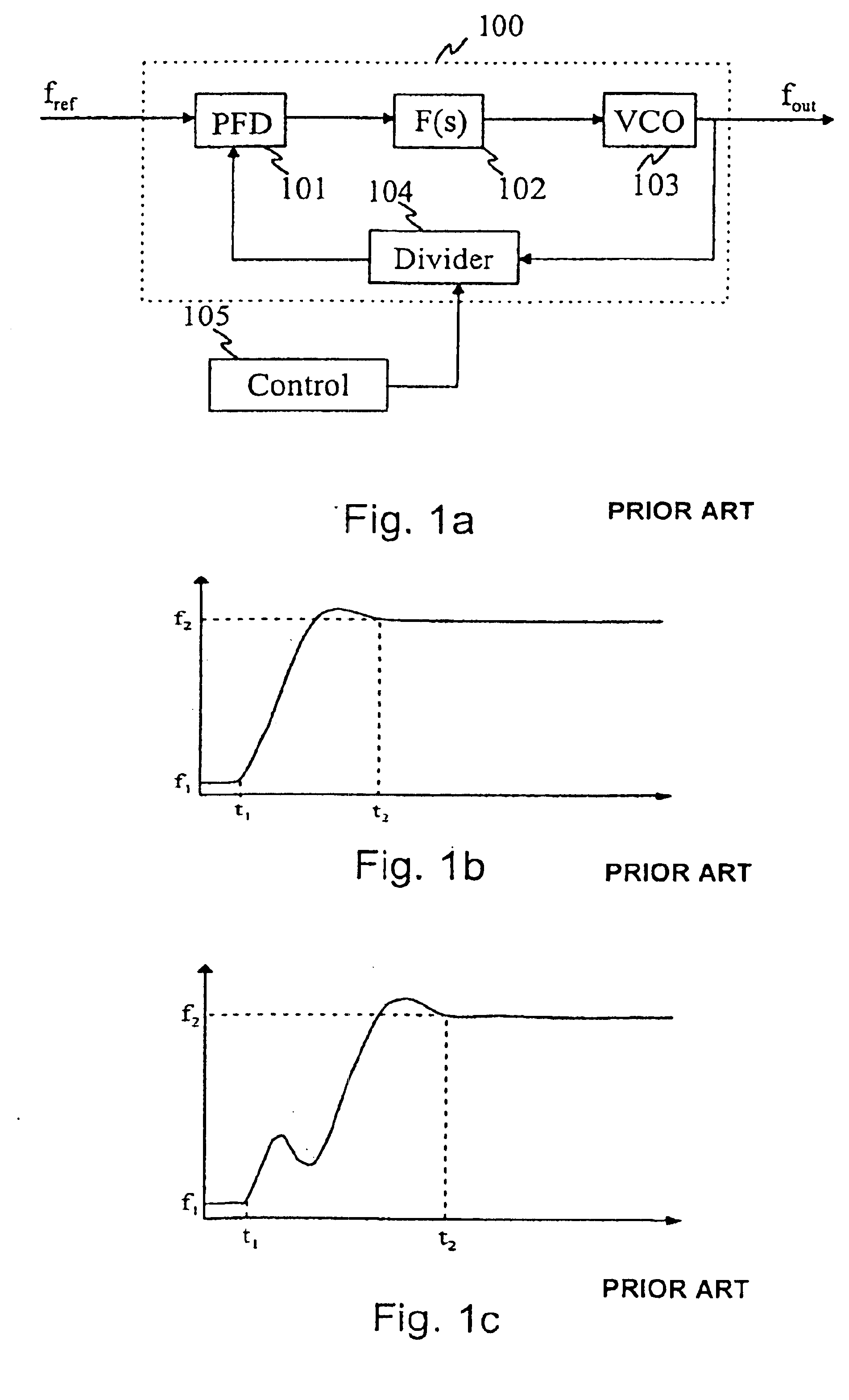
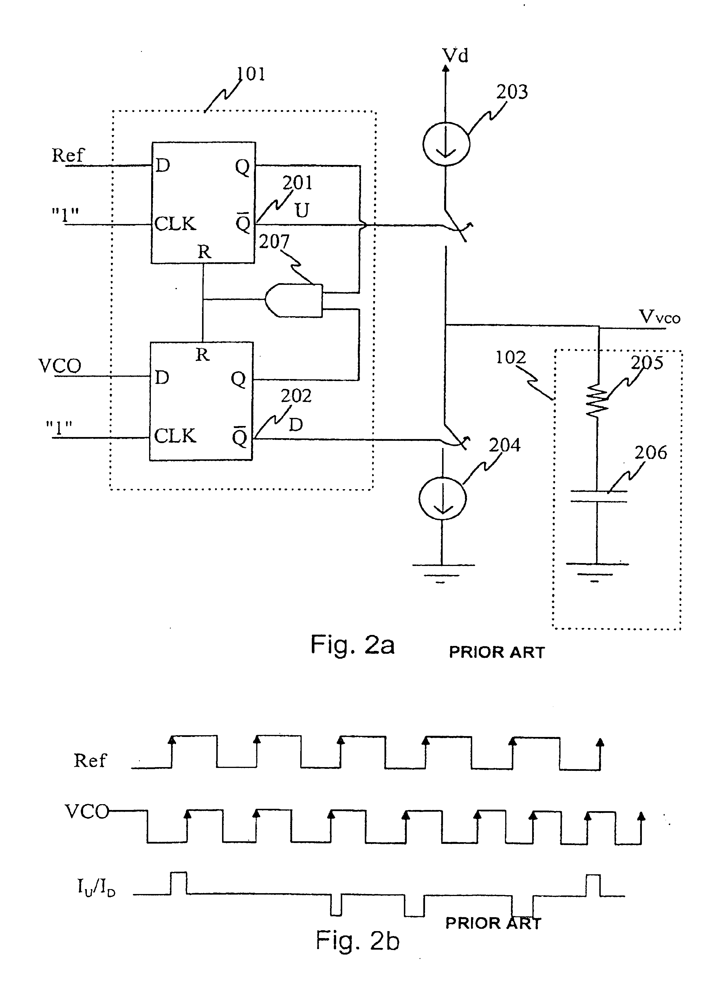
[0029]The prior art was described with reference to FIGS. 1a to 3a. In the following, the invention will be described in greater detail with reference to FIGS. 3b to 6.

[0030]FIG. 3b shows an operating range of a phase detector according to one alternative embodiment of the invention. In a phase comparison range [0,2π] a first pair of charge pumps generates a first control voltage for a voltage controlled oscillator, which control voltage (0-+Vmax) is proportional to ...


PUM


Abstract

A method and a device for reducing cycle slips resulting from frequency hops in a wireless communication device. In the method, a first signal pulse is received, which first signal pulse is either said reference signal pulse or said signal pulse to be compared, a second signal pulse is received, which second signal pulse is from another source than said first signal pulse, a control voltage is generated for controlling a voltage controlled oscillator in response to a phase difference between said first received and said second received signal pulses. At a time instant between the reception of said first and said second signal pulses, a constant voltage is added to said control voltage on receiving additionally one signal pulse, which is the same type as said first signal pulse. After receiving said second signal pulse, said constant voltage is removed from said control voltage on receiving at least one signal pulse, which is the same type as said second signal pulse.

Description

FIELD OF THE INVENTION[0002]The present invention relates to a method and a device for improving the efficiency of a frequency synthesizer, and particularly but not necessarily, for reducing cycle slips in connection with frequency hops.BACKGROUND ART[0003]Because of new TDMA (Time Division Multiple Access) and TDD (Time Division Duplex) standards, such as HSCSD, GPRS, WCDMA / TDD and Bluetooth, determining a signal settling time has a key role in wireless communications systems. In said standards, a time window between a TX slot and an RX slot is getting shorter and shorter.[0004]Transceivers in radio-frequency communications systems, such as mobile systems, employ frequency synthesizers for generating a radio-frequency signal. Previous implementations have employed a so-called integer-N synthesizer, in which a feedback divider divides a frequency arriving in a phase detector by an integer N. When the divider input has received N pulses, the output provides one pulse.[0005]The freque...

Claims


Application Information

Patent Timeline
Patent Type & Authority Patents(United States)
IPC IPC(8): H03L7/089H03D13/00H03L7/18H03L7/08H03L7/16H03L7/197H04L7/033
CPCH03D13/004H03L7/18H03L7/0891
Inventor ASIKAINEN, KALLERINTAMAKI, SAMI
Owner NOKIA CORP
Why Eureka
Try Eureka