Vehicular manipulation apparatus

Active Publication Date: 2019-08-22
DENSO CORP
View PDF0 Cites 0 Cited by
  • Summary
  • Abstract
  • Description
  • Claims
  • Application Information

AI Technical Summary

Benefits of technology

The present invention provides a vehicle manipulation apparatus that reduces delays when manipulating the apparatus to change displayed images. The apparatus includes a manipulation unit, communication unit, display unit, and controller. The manipulation unit selects and inputs control parameters for the different apparatus, the communication unit sends manipulation information to the apparatus and receives the set value of the apparatus, and the display unit shows the set value digitally. The controller controls the image displayed on the display unit using the set value. In cases where the manipulation amount exceeds a threshold, the controller broadens the change width between steps to reduce delay. This allows for a quick display of the change step-by-step, making the manipulation process less strang to the user.

Problems solved by technology

Such a configuration takes a period of time from when the rotary switch is manipulated to when the latest set temperature is displayed, providing a user with a feeling of strangeness.
This causes the user to feel strange.

Method used


Image

  • Vehicular manipulation apparatus
  • Vehicular manipulation apparatus
  • Vehicular manipulation apparatus

Examples


first embodiment

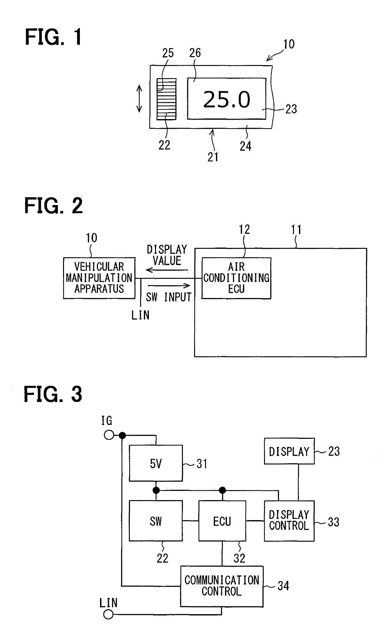
[0028]The following describes a first embodiment according to the present disclosure with reference to FIGS. 1 to 13. The vehicular manipulation apparatus 10, which is mounted to a vehicle, is an apparatus to change and input a set value of a predetermined control parameter in a vehicular air-conditioning apparatus 11. The vehicular manipulation apparatus 10 is arranged in a center console of the vehicle. The vehicular manipulation apparatus 10 changes the setting of the temperature of a conditioned air of the vehicular air-conditioning apparatus 11, for example, as a predetermined control parameter. The vehicular manipulation apparatus 10 is thus also referred to as an air conditioner panel. As shown in FIG. 1, the vehicular manipulation apparatus 10 includes a casing 21, a rotary switch 22, and a display unit 23, as members constituting an external appearance.

[0029]The casing 21 is a box-like member for internally accommodating the respective members constituting the vehicular man...

second embodiment

[0077]The following describes a second embodiment of the present disclosure with reference to FIGS. 14 and 15. The present embodiment is characterized in that the configuration of a manipulation unit (or manipulation switch, manipulation interface) is realized with a capacitive type slide switch. As shown in FIG. 14, a slider 40, which is an electrostatic capacity type slide switch, can perform an input with a user's touching manipulation.

[0078]The slider 40 has an area which can be manipulated; the area is long and thin. The area includes a slide manipulation area 42 in the center, an up manipulation area 41 in the upper portion, and a down manipulation area 43 in the lower portion.

[0079]In the slide manipulation area 42, the set value increases when the position of a fingertip is changed by the fingertip sliding upward while touching the slide manipulation area 42. Similarly, the set value decreases when the position of the fingertip is changed by the fingertip sliding downward wh...


PUM


Abstract

A vehicular manipulation apparatus, which manipulates a different apparatus, includes a manipulation unit, a communication unit, a display unit, and a controller. The manipulation unit accepts a manipulation and inputs a set value step-by-step for controlling the different apparatus. The communication unit communicates with the different apparatus, transmits manipulation information to the different apparatus, and receives a set value of the different apparatus. The display unit digitally displays the set value. The controller controls an image on the display unit using the set value. In displaying change due to the manipulation step-by-step, the controller broadens a change width between steps in cases where the manipulation amount within a threshold period of time is equal to or greater than a threshold manipulation amount, as compared with cases where the manipulation amount within the threshold period of time is less than the threshold manipulation amount.

Description

CROSS REFERENCE TO RELATED APPLICATION[0001]This application is based on Japanese Patent Application No. 2016-141644 filed on Jul. 19, 2016, the disclosure of which is incorporated herein by reference.TECHNICAL FIELD[0002]The present disclosure relates to a vehicular manipulation apparatus for manipulating an apparatus mounted on a vehicle.BACKGROUND ART[0003]There is conventionally known a manipulation apparatus, for example, as described in Patent literature 1. The manipulation apparatus in Patent literature 1 includes a rotary switch which partly projects from the upper surface of the casing and is rotated by a manipulator, and a rotation detection mechanism for detecting the rotation state of the rotary switch. A display unit is installed adjacent to the rotary switch; when a rotating manipulation is made to the rotary switch, the numerical value displayed on the display unit changes or the display content changes according to the rotating manipulation.PRIOR ART LITERATUREPatent...

Claims


Application Information

Patent Timeline
IPC IPC(8): B60H1/00B60R16/037B60K35/00G06F3/0484G06F3/0362
CPCB60H1/00585B60R16/037B60K35/00G06F3/04847G06F3/0362B60K2370/126B60K2370/12B60K2370/1537B60K2370/168B60K2370/128B60K2370/1446B60H1/00B60R16/02G06F3/0487G06F3/0484B60H1/00985B60H1/0065B60K35/10B60K2360/11B60K2360/126B60K2360/1442B60K35/81B60K35/28B60K35/212B60K2360/128B60K2360/168B60K2360/1446
Inventor TAKENAKA, KENICHIOTA, YUKIHIDE
Owner DENSO CORP
Why Eureka
Try Eureka