
Left-turn lane channelization and signal design method based on straight lane in direction

A technology of left-turn lane and signal design, applied in the direction of controlling traffic signals, traffic control systems of road vehicles, instruments, etc., can solve problems such as damage to the central isolation belt and damage to traffic facilities

Active Publication Date: 2020-07-07
DALIAN JIAOTONG UNIVERSITY
View PDF7 Cites 15 Cited by
  • Summary
  • Abstract
  • Description
  • Claims
  • Application Information

AI Technical Summary

Problems solved by technology

Finally, for intersections with a central isolation zone, if the method of turning left by borrowing the opposite lane is used, the central isolation zone will be destroyed and the original traffic facilities will be damaged

Method used


Image

  • Left-turn lane channelization and signal design method based on straight lane in direction
  • Left-turn lane channelization and signal design method based on straight lane in direction
  • Left-turn lane channelization and signal design method based on straight lane in direction

Examples


Embodiment 1

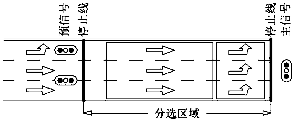
[0121] At the entrance of the intersection, according to the phase sequence, the through lane in this direction is used, and the left-turning vehicle is guided to the front of the sorting area in advance through pre-signal control, and the through vehicle is behind and divided into its own area. Wait for the main signal pass signal. This method needs to set a separate left-turn phase, and the number of borrowed lanes can be increased or decreased according to the actual situation. see details image 3 shown.

[0122] Borrowing the scheme of straight lanes in this direction, at the entrance lanes, each lane is generally separated by a white dotted line, allowing vehicles to change lanes at the entrance lanes, the purpose of which is to separate left-turning vehicles from straight-going vehicles. Depend on image 3 It can be seen that there is a stop line at the pre-signal, the area between the pre-signal and the main signal is the general sorting area, and the left-turning v...

Embodiment 2

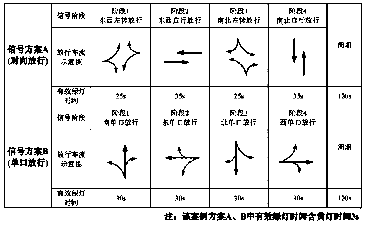
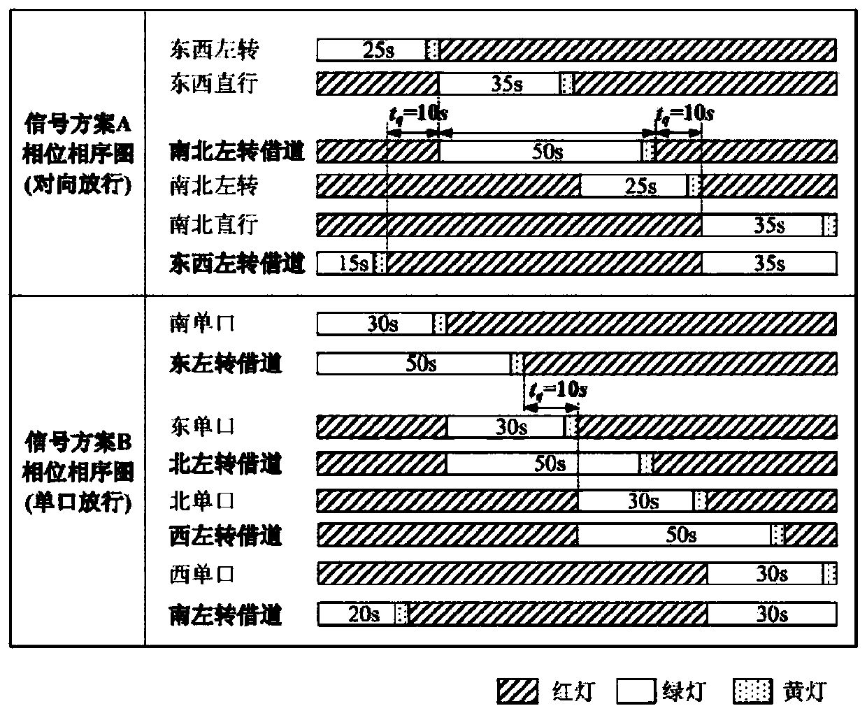
[0152] Such as Figure 7-11 As shown, through the design and simulation of three kinds of left-turn lanes at an example intersection: there is a left-turn by borrowing the through lane in this direction, a left-turn by borrowing the through lane of the adjacent oncoming vehicle, and a traditional left-turn lane design. Lane emission ratio and traffic capacity of the scheme.

[0153] (1) Intersection investigation

[0154] 1) Intersection location and flow

[0155] Select the intersection of Changchun Road and Wusi Road in Xigang District, Dalian City. Changchun Road is a north-south two-way lane, and Wusi Road is a one-way lane from east to west. The lane width of the south entrance road is 3.0 meters, and the lane width of the south exit road is 3.5 meters. On the south side of the intersection is the Changchun Bridge Viaduct. The weaving area between the lower bridge entrance of the viaduct and the road on the same side is 79.9 meters away from the parking line of the sou...


PUM

PropertyMeasurementUnit
Lengthaaaaaaaaaa

Abstract

The invention provides a left-turn lane channelization and signal design method based on a straight lane in the direction, and the method comprises the following steps: 1, carrying out the phase timing of a main signal according to a timing method, and obtaining the period of the main signal and the entrance left-turn green light time and straight green light time of a designed pre-signal; 2, determining left-turn effective green light time of the pre-signal; 3, determining the length of a sorting area of the left-turn vehicle; 4, determining the sorting area length and the total sorting arealength of the straight-going vehicles; 5, determining key time; 6, determining the effective straight green light time of the pre-signal; 7, after each area is divided, enabling the vehicle to pass ina timing manner according to the main signal and the pre-signal. The method provided by the invention has obvious advantages in terms of lane emission proportion and traffic capacity level.

Description

technical field [0001] The invention relates to a channelization and signal design method of a left-turn lane using a straight lane in this direction. Background technique [0002] Most of the conflict points at signalized intersections come from the impact of left-turn traffic flow. In the study on the determination of the storage length of left-turn lanes at signalized intersections, Qi et al. considered that all vehicles waiting in line to turn left have two parts: one part is the red light The queue during the period; the other part is the queue remaining after the previous green light ended. Wei et al. studied the factors that cause lane changes when vehicles turn left at signalized intersections, and pointed out that there are two forms of lane change behavior for left turns: one is to change lanes during the left turn at the intersection; the other is to change lanes after completing the left turn After changing lanes. Yao gave three signal phase schemes when studyi...

Claims


Application Information

Patent Timeline
IPC IPC(8): G08G1/07G08G1/08G08G1/083
CPCG08G1/07G08G1/08G08G1/083
Inventor 于泽文郭瑞军张璐瑶王倩李月
Owner DALIAN JIAOTONG UNIVERSITY
Learn More