A magnetic levitation train track and its joint device

A technology for maglev trains and joint devices, applied in the field of maglev, can solve problems such as increased project cost, limited expansion and contraction, and increased construction difficulty, so as to prevent excessive rail gaps, ensure reliability and safety of use, and increase the range of change Effect

Active Publication Date: 2019-06-18
BEIJING ENTERPRISES HLDG MAGLEV TECH DEV
View PDF8 Cites 0 Cited by
  • Summary
  • Abstract
  • Description
  • Claims
  • Application Information

AI Technical Summary

Problems solved by technology

One of the important issues is that in the design of line bridges in special locations (such as crossing the double-line overpass at the front of Xiaoyuan Station on S1 Line, and crossing the Yongding River Bridge), it is necessary to adopt a long-span continuous beam design scheme. However, the traditional maglev track joint The device realizes telescopic adjustment by reserving a longitudinal gap between adjacent rails, and the amount of telescopic expansion is extremely limited, which cannot meet the telescopic requirements of such a large-span continuous beam
However, this method will greatly increase the project cost and increase the difficulty of construction

Method used


Image

  • A magnetic levitation train track and its joint device
  • A magnetic levitation train track and its joint device
  • A magnetic levitation train track and its joint device

Examples


Embodiment 1

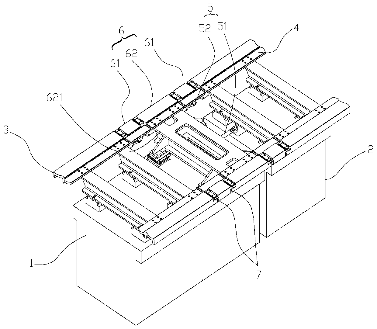
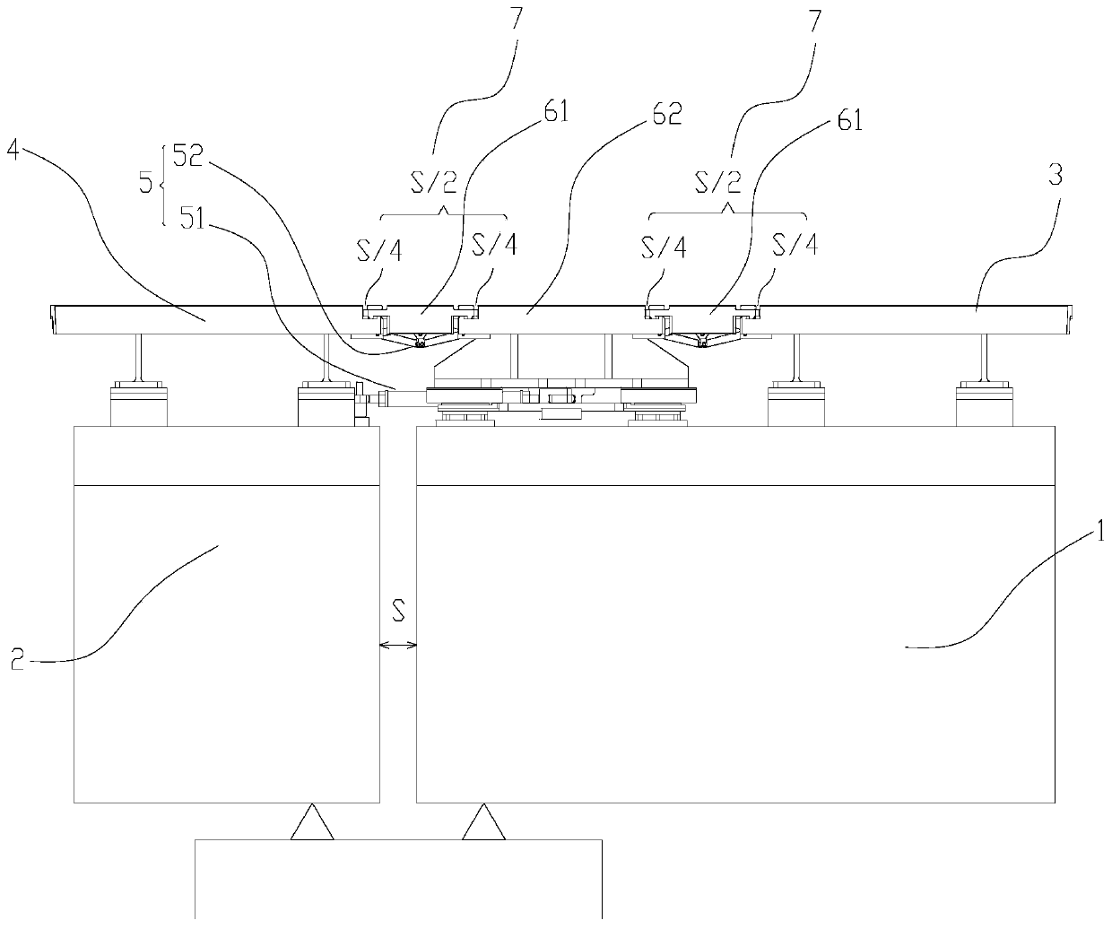
[0055] like figure 1 and figure 2 As shown, in the first specific embodiment, the connecting rail 6 includes a moving rail 62 and joints 61 longitudinally movably connected to the two ends of the moving rail 62, and the joints 61 at both ends are connected to the first guide rail 3 and the second guide rail 4 respectively. Longitudinal movable connection; there is a gap at both ends of the joint 61 between the first guide rail 3 and the moving rail 62, and the gaps at both ends jointly form the rail gap 7 between the first guide rail 3 and the moving rail 62; between the moving rail 62 There are gaps at both ends of the joint 61 with the second guide rail 4 , and the gaps at both ends together form a rail gap 7 between the moving rail 62 and the second guide rail 4 . When the distance between the first track beam 1 and the second track beam 2 changes, the rail gap distribution mechanism 5 drives the moving rail 62 to move longitudinally, and then adjusts the gap between the ...

Embodiment 2

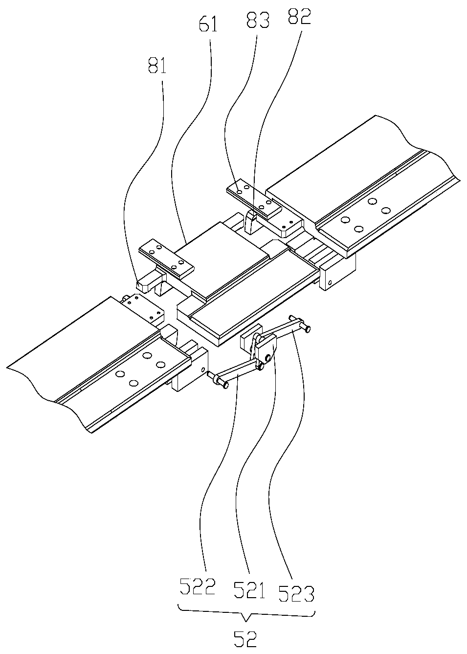
[0067] like Figure 6 and Figure 7 As shown, in the second specific embodiment, the connecting rail 6 of the present invention may include a joint 61 and at least two moving rails 62, and adjacent moving rails 62 may be connected by joints 61, and the adjacent moving rails A rail gap 7 is formed between the rails 62, that is, the inside of the connecting rail 6 may also have a rail gap 7, or each moving rail 62 may be connected longitudinally and sequentially to form a rail body, as the connecting rail 6; the two ends of the connecting rail 6 pass through the joint 61 are respectively connected with the first guide rail 3 and the second guide rail 4, and the joints corresponding to each joint 61 can adopt longitudinal movable connection, and the gaps at both ends of each joint 61 jointly form the rail seam 7; the rail seam distribution mechanism 5 can drive each moving rail 62 to move longitudinally, to limit each rail gap 7.

[0068] The joint 61 can adopt the structure in...


PUM


Abstract

The invention provides a maglev train track and a joint device of the same. Adjusting amount of a joint track seam can be increased and demands for large-span continuous beams can be met. The joint device is used for connecting a first guide rail arranged on a first rail gap and a second guide rail arranged on a second rail gap; the first track beam is adjacent to the second track beam; the joint device is formed by a rail gap distribution mechanism and a connection rail arranged on the first track beam; two ends of the connection rail are respectively connected with the first guide rail and the second guide rail in a longitudinal and movable way; rail gaps are arranged between the connection rail and the first guide rail and the second guide rail; and when a gap between the first track beam and the second track beam is changed, the rail gap distributing mechanism drives the connection rail to longitudinally move, so each rail gap can be adjusted. Use demands of large-span continuous beams can be met, and excessive individual rail gaps can be prevented by the rail gap distribution mechanism; and use reliability and safety can be guaranteed.

Description

technical field [0001] The invention relates to the technical field of magnetic levitation, in particular to a magnetic levitation train track and a joint device thereof. Background technique [0002] The tracks of medium and low-speed maglev trains are firstly assembled by connecting the F-shaped rails with high-strength bolts through the transverse sleepers to form a rail row. track line. [0003] With the above-mentioned structure, between each rail row and the rail row, not only must be installed and aligned in the three dimensions of longitudinal (X), transverse (Y), and vertical (Z), but also in the longitudinal (X) direction. Expansion and contraction caused by thermal expansion and contraction. [0004] The joint devices in the prior art are usually fasteners (such as type II joints and type I joints), which are fastened on two adjacent rails and fixed by means of high-strength bolts and the like. With this type of joint device, it is necessary to leave a certain ...

Claims


Application Information

Patent Timeline
Patent Type & Authority Patents(China)
IPC IPC(8): E01B25/30
CPCE01B25/30
Inventor 罗昆周晖杨登峰张学山张兴华
Owner BEIJING ENTERPRISES HLDG MAGLEV TECH DEV
Why Eureka
Try Eureka