
Single ended tuning of a differential power amplifier output

a power amplifier and output technology, applied in the field of single-ended tuning of differential power amplifier output, can solve the problems of consuming too much precious space within the transmitter chip of effective integrated inductor, and affecting the performance of the amplifier

Inactive Publication Date: 2005-01-18
GATX VENTURES
View PDF6 Cites 29 Cited by
  • Summary
  • Abstract
  • Description
  • Claims
  • Application Information

AI Technical Summary

Benefits of technology

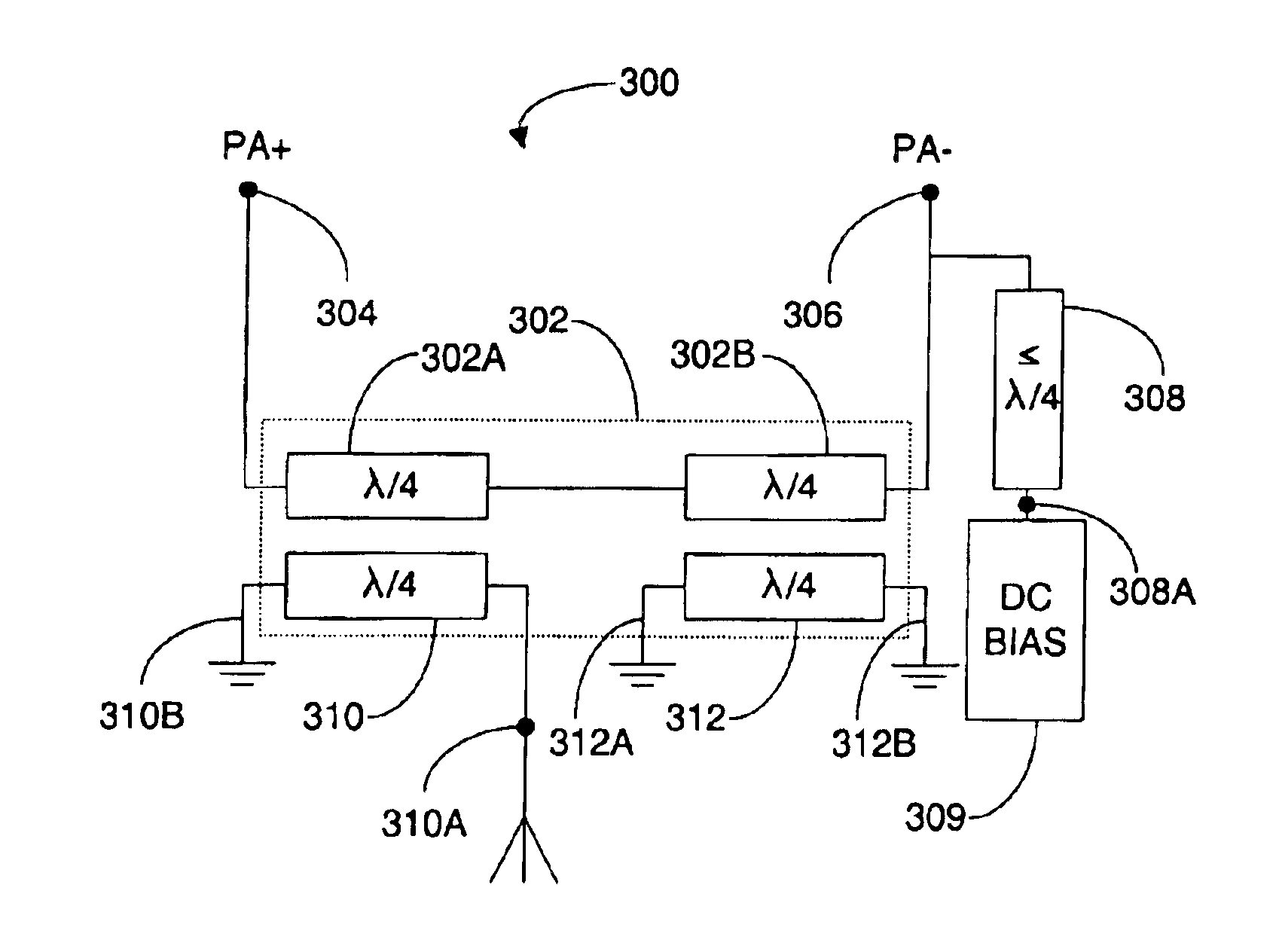
In one embodiment, the system and method can include a balun. The balun includes a primary portion and a secondary portion. The primary portion includes the first conductor. The secondary portion includes a third conductor and a fourth conductor. The third conductor and the fourth conductor each have a length equal to about one quarter wavelength. The fourth conductor can be coupled between a ground potential and an antenna port. The third conductor and the fourth conductor can be substantially aligned with the first conductor so as to maximize a signal cross coupling from the first conductor to the third conductor and the fourth conductor.
The present invention provides the advantage of a single compensation device that provides a balanced compensation for the parasitic output capacitance of the differential amplifier outputs.

Problems solved by technology

These external connections result in at least some parasitic capacitance in the output of the PA that cannot be eliminated in or efficiently compensated for on the chip.
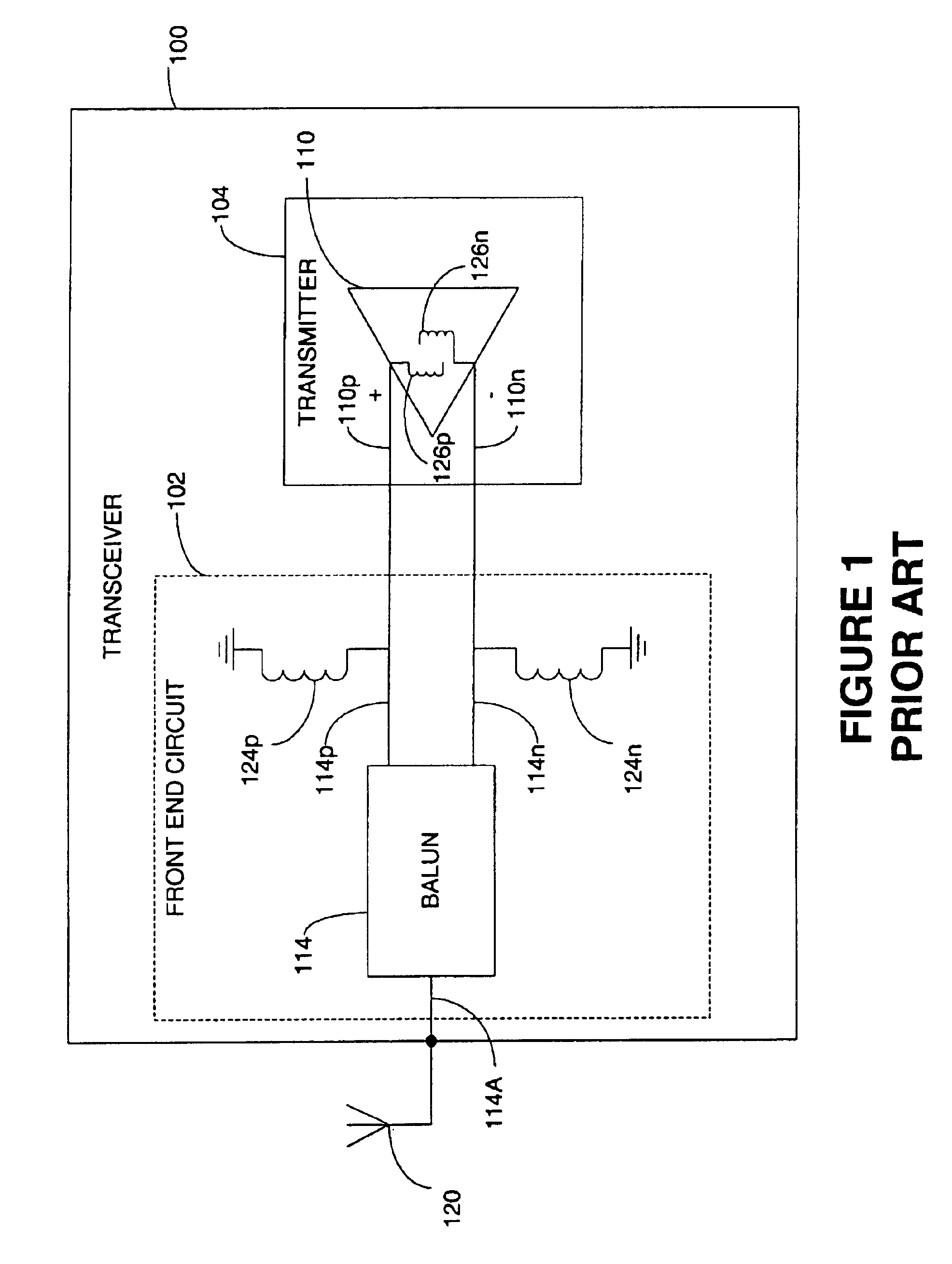
However, an effective integrated inductor consumes too much precious space within the transmitter chip 104.
Therefore placing an inductor within the transmitter 104 is an inefficient use of the available space on the chip 104 and therefore significantly increases the cost.
Further, the inductive component variations between manufacturers or even slight variations in the installation of the inductors in the front-end circuit can require still additional tuning.
Nominally, the PA output impedance is designed to be entirely resistive RPA out, but ultimately at least some on-chip parasitic capacitance XPA out cannot be avoided.
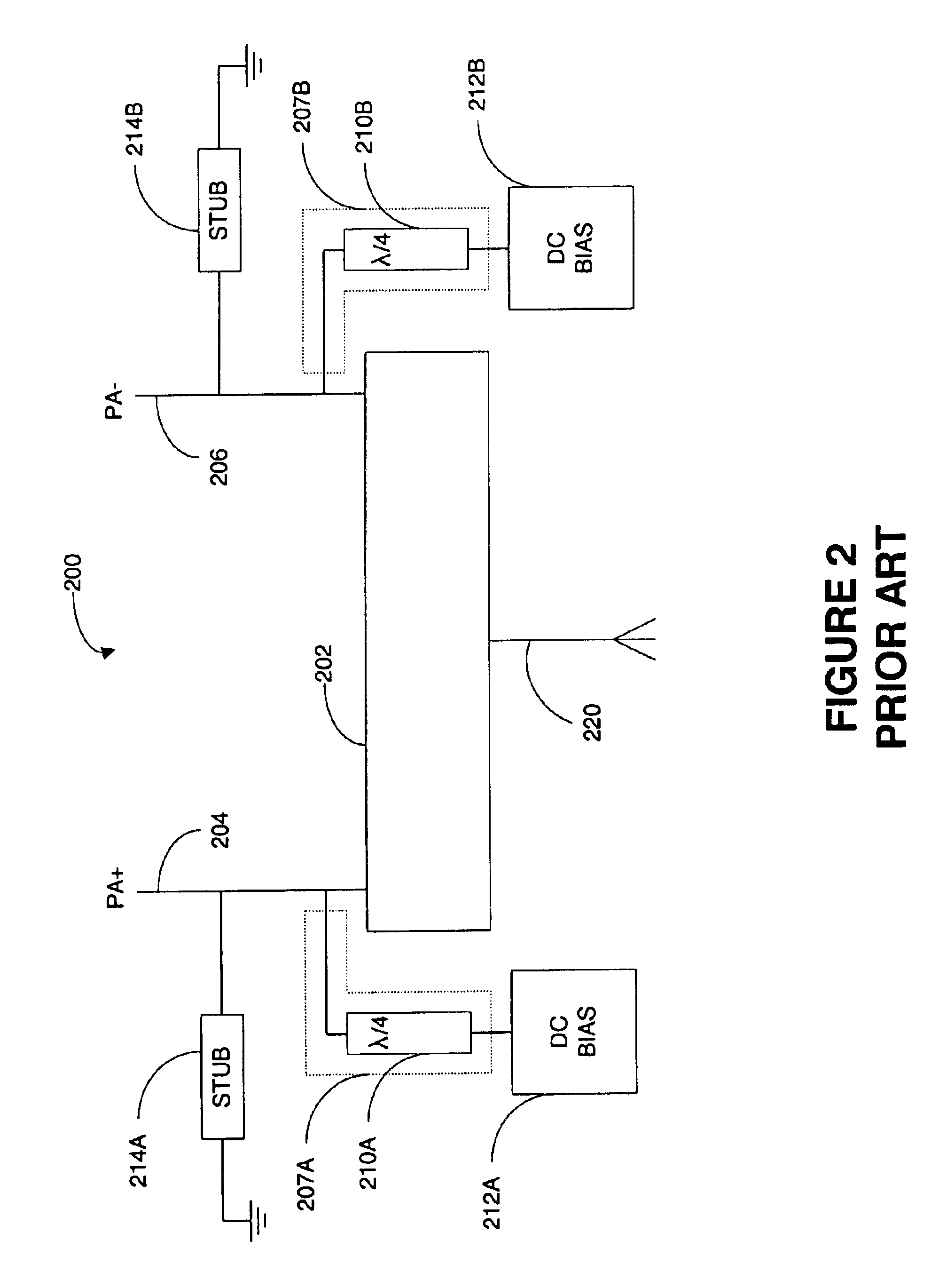
If the two tuning stubs 214A, 214B were not precisely the same dimensions, they could create additional imbalances on the PA output.
However, each of these stubs can provide yet additional capacitance and additional variation that could cause still more imbalances that must be corrected.

Method used


Image

  • Single ended tuning of a differential power amplifier output
  • Single ended tuning of a differential power amplifier output
  • Single ended tuning of a differential power amplifier output

Examples


Embodiment Construction

Several exemplary embodiments for single-ended tuning of a differential power amplifier (PA) output will now be described. It will be apparent to those skilled in the art that the present invention may be practiced without some or all of the specific details set forth herein.

The prior art approaches required each of the differential outputs of a differential PA output to be manipulated to compensate for the parasitic capacitance. The manipulations typically included one or more RF stubs added to the PA output circuitry. The prior art RF stubs were required to be very precise and very symmetrical to maintain the balance of the differential outputs. Any variation in the RF stubs could result in additional parasitic capacitance or parasitic conductance or other imbalances.

One embodiment of the present invention includes coupling the differential PA outputs with a conductive line that has a length that is a function of the wavelength divided by two (i.e., λ / 2, λ, 3 λ / 2, etc.). Conductor...


PUM


Abstract

A system and method for compensating a parasitic capacitance on a differential amplifier output includes a first differential output and a second differential output of the differential amplifier. The first differential output coupled to the second differential output by a first conductor that has a length of about one half wavelength. The first and the second differential outputs have a parasitic capacitance that can be measured. A second conductor is coupled to the first differential output. The second conductor having a length that is less than or equal to about one quarter wavelength and has an inductive reactance that offsets a capacitive reactance of the parasitic capacitance.

Description

BACKGROUND OF THE INVENTION1. Field of the InventionThe present invention relates generally to systems and methods of tuning power amplifier outputs and more particularly, to systems and methods for tuning a single output of a differential power amplifier.2. Description of the Related ArtTransceiver power efficiency is greatly dependant on the efficiency of the transmitter power amplifier (PA). An efficient PA converts as much of the bias current to RF output as possible. PA efficiency is especially important in portable transceiver systems that rely on a portable power source (e.g., battery) or other transmitters that have a limited power supply. Many portable transmitters are manufactured as highly integrated circuits (i.e., transmitter on a chip) so as to exploit the power efficiencies of integrated circuit design.Some of the potential transmitter inefficiencies can be eliminated or significantly reduced in the design of the integrated power amplifier components. However, an inte...

Claims


Application Information

Patent Timeline
Patent Type & Authority Patents(United States)
IPC IPC(8): H03F1/08H01P5/10H03F3/60H03F3/45
CPCH01P5/10H03F1/08H03F3/60H03F3/45475H03F2200/09
Inventor KOEPPE, JAMESMCKAY, TOMPOSTOYALKO, VAS
Owner GATX VENTURES
Learn More