
Flexible thin battery and method of manufacturing same

a thin battery, flexible technology, applied in the direction of cell components, final product manufacturing, sustainable manufacturing/processing, etc., can solve the problems of complex process, compromising the effectiveness of package seals, and challenges to tabs

Inactive Publication Date: 2005-01-04
ENERGIZER BRANDS
View PDF20 Cites 65 Cited by
  • Summary
  • Abstract
  • Description
  • Claims
  • Application Information

AI Technical Summary

Benefits of technology

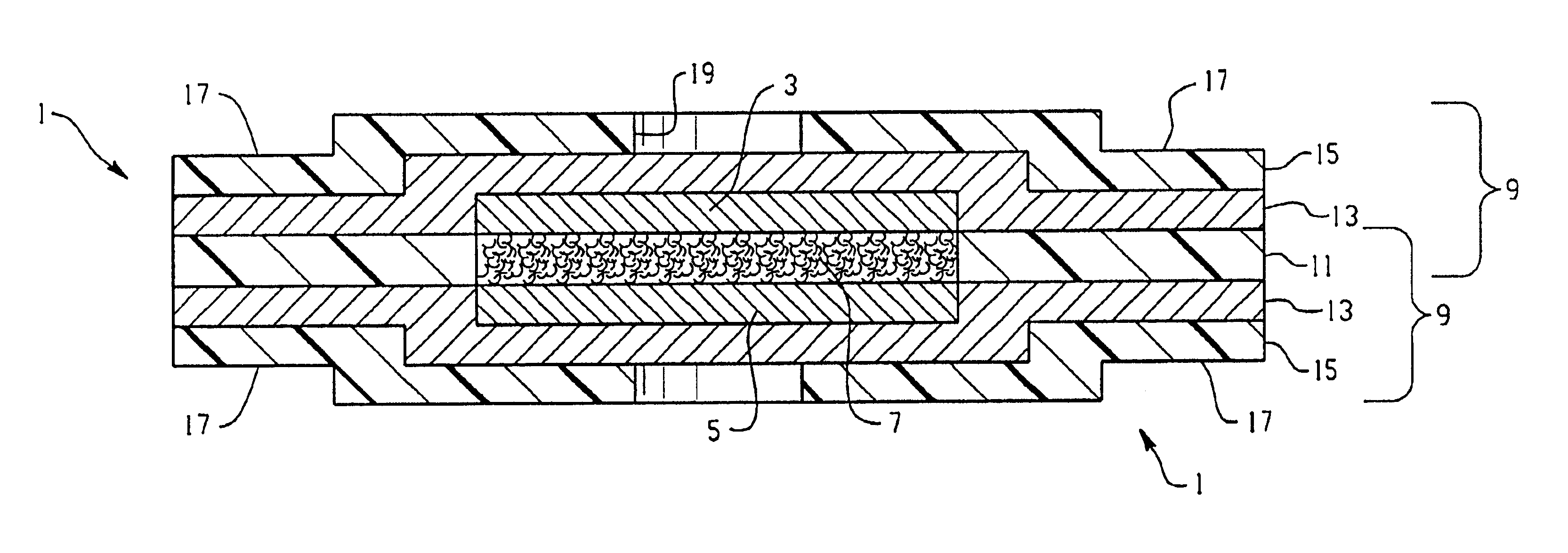
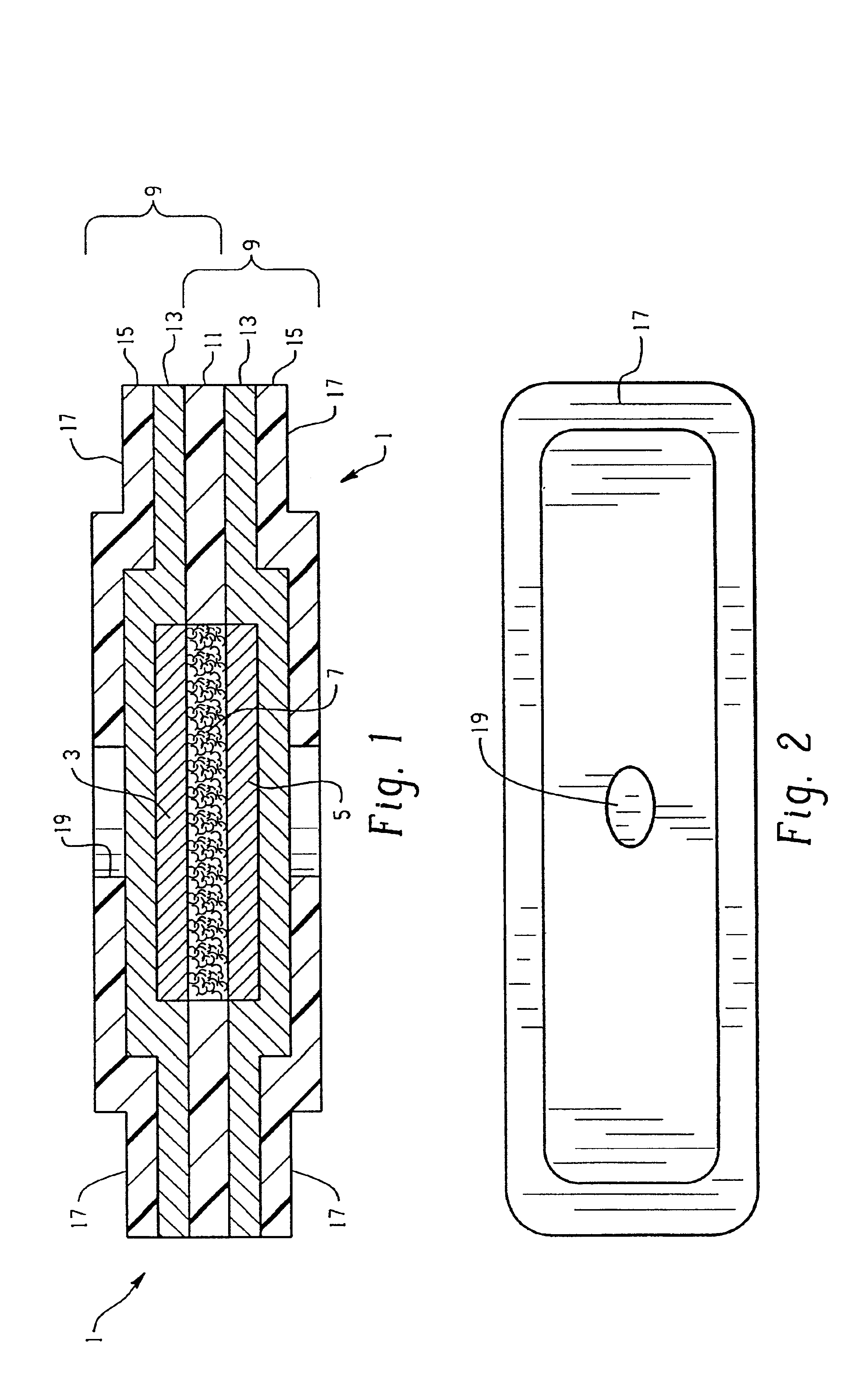
A thin, preferably flexible battery is provided comprising an anode, a cathode and electrolyte contained within a sealed housing or package and contacts to provide current from the battery to the battery powered device. The contacts are integral with the material forming the battery package or housing, thereby avoiding the need for tabs to pass through a sealed area of the battery package or housing.

Problems solved by technology

The tabs present a challenge in this type of construction for several reasons.
This is a complex process.
The extension of the tab from the interior to the exterior of the battery packaging can compromise the effectiveness of the package seal in the area where the tab must pass.

Method used


Image

  • Flexible thin battery and method of manufacturing same
  • Flexible thin battery and method of manufacturing same
  • Flexible thin battery and method of manufacturing same

Examples


example 1

An electrode assembly was constructed consisting of a cathode, anode and separator. The cathode consisted of iron pyrite, conductor and binder combined into a slurry and intermittently roll coated onto both sides of an aluminum foil to form a planar sheet 37 millimeters×39.5 millimeters×0.17 millimeters. The anode consisted of a lithium foil sheet 38 millimeters×38 millimeters×0.152 millimeters. An annealed nickel tab was cold welded at one end to the lithium foil. Celgard 2400 separator was then heat sealed around the combined lithium foil and nickel tab assembly, leaving a portion of the nickel tab protruding beyond the separator seal perimeter. The internal anode contact was formed by taking a sheet of laminate available from Pharma Center Shelbyville, product designation 95014, and selectively removing a portion of the heat seal layer to expose the inner surface of the aluminum layer. The protruding end of the nickel tab was placed in direct contact with this exposed aluminum su...

example 2

An anode, cathode, separator and associated internal tabs were assembled as in Example 1. The internal contacts for the anode and the cathode were formed from two distinct sheets of laminate as in Example 1. An open pouch containing the battery components was formed by heat sealing the two separate sheets together and electrolyte was introduced into the open pouch as in Example 1. The opening in the pouch was then heat sealed. External anode and cathode contacts were formed on a portion of each laminate sheet extending beyond the pouch seal perimeter. Material from either the protective polymer layer or the heat sealable polymer layer or both were selectively removed to expose one or both surfaces of the conductive aluminum layer of the laminate. Pressure was applied to the major surfaces of the pouch battery to assure good contact between all the cell components. The external contacts were then connected to a load and the battery was discharged at a continuous drain of 7 milliamps ...


PUM

PropertyMeasurementUnit
Electrical conductivityaaaaaaaaaa
Flexibilityaaaaaaaaaa
Electrical conductoraaaaaaaaaa

Abstract

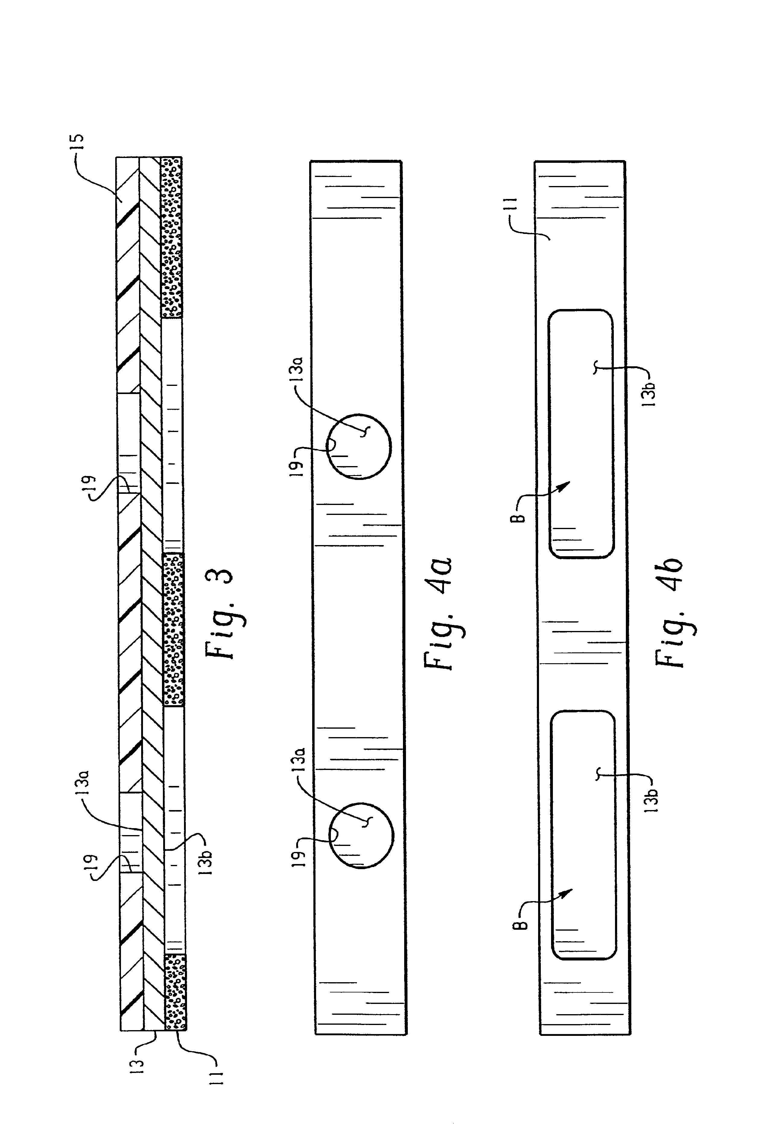
A tabless battery housed in a sealed package is provided. The packaging material for the battery comprises a conductive material and a sealing material. At least a portion of the interior surface of the conductive material is exposed to form an internal contact between at least one electrode and the conductive material. At least a portion of the exterior surface of the conductive material is also exposed to form an external contact between the electrode and the device.

Description

FIELD OF THE INVENTIONThis invention relates to a flexible thin battery and a method for making such a battery. More specifically, this invention relates to a flexible thin battery wherein the electrode contacts are integral with the housing for the battery.BACKGROUND OF THE INVENTIONFlexible thin batteries typically comprise contacts for carrying current between the battery electrodes and the device powered by the battery. These contacts are generally in the form of tabs, one or more discrete structures connected at one end to the electrode active material or the electrode substrate and extending from the interior of the battery to the exterior of the battery. Flexible thin batteries further generally comprise a housing or package sealed about the battery perimeter to enclose the electrodes, electrolyte and separator components. The package seal is typically formed by the application of heat or pressure or both to a sealable material to join the opposing surfaces of the package mat...

Claims


Application Information

Patent Timeline
IPC IPC(8): H01M2/02H01M10/04H01M10/05H01M10/058H01M10/0585H01M50/119H01M50/121H01M50/129H01M50/548H01M50/562
CPCH01M2/0215H01M2/0275H01M10/0436Y10T29/49108H01M2300/0025H01M2/0287Y02E60/10H01M50/124Y02P70/50H01M50/562H01M50/121H01M50/129H01M50/548H01M50/119
Inventor LANGAN, RICHARDFEDDRIX, FRANK
Owner ENERGIZER BRANDS
Learn More