
Structural reinforcement using composite strips

a composite strip and structural reinforcement technology, applied in the field of structural reinforcement strips, can solve the problems of time-consuming methods, system preparation and curing, and adhesives that cannot reach the design strength, and achieve the effects of reducing potential damage to the underlying structure, easy to carry by a single person, and easy cutting

Inactive Publication Date: 2004-11-02
WISCONSIN ALUMNI RES FOUND
View PDF28 Cites 14 Cited by
  • Summary
  • Abstract
  • Description
  • Claims
  • Application Information

AI Technical Summary

Benefits of technology

The invention is a structural reinforcing strip that can be easily carried, cut, and attached to structures using fasteners. The strip includes elongated continuous parallel fibers and nondirectional fibers distributed throughout the strip. The strip can be coiled for easy transport and can be uncoiled and cut to length for use. The use of nondirectional fibers helps prevent fractures and allows for greater strength and ductility of the structure. The invention provides several advantages over previous reinforcing methods, including rapid repair times, easy use in field conditions, and superior strength per unit size and weight.

Problems solved by technology

This method is time-consuming since it can take days per application to sandblast, clean, and smooth the concrete so that it is suitable for bonding.
Following the application of the adhesive, the composite strip must be left for at least a day, and often the adhesive will not reach design strength for approximately a week.
These systems require the same careful and time-consuming preparation and curing as in the case of bonding a prefabricated composite strip to the concrete.
In situations where it is necessary to make extremely rapid repairs to structures, e.g., where military operations require rapid repairs of bridges, or disaster relief efforts require that wall or ceiling beams be quickly reinforced, the foregoing adhesive bonding methods are clearly insufficient owing to the curing time needed for the adhesive.
These are generally unsuitable for rapid repairs owing to the time needed to suitably affix the tendons to the structure, and the size and weight of the tendons generates additional problems because they are difficult to transport and install by military and / or emergency personnel with minimal tools and manpower.
The use of composite strips in place of metal tendons would ease transportability and weight concerns, but the use of mechanically attached composite strips has not been accepted because the stress concentration points created by the fasteners tends to greatly decrease the strength of the strips.
The high loads at the fastener holes in the strips cause ripping, which propagates through the strips until failure occurs.
Thus, mechanical attachment of composite strips has thus far been primarily limited to the use of anchorages (e.g., anchor bolts or cover plates) at the ends of adhered composite strips, not to serve as the primary load transfer mechanism between the concrete and the composite strip, but to prevent catastrophic brittle failure of adhered strips when the adhesive bond separates from the underlying structure.

Method used


Image

  • Structural reinforcement using composite strips
  • Structural reinforcement using composite strips
  • Structural reinforcement using composite strips

Examples


Embodiment Construction

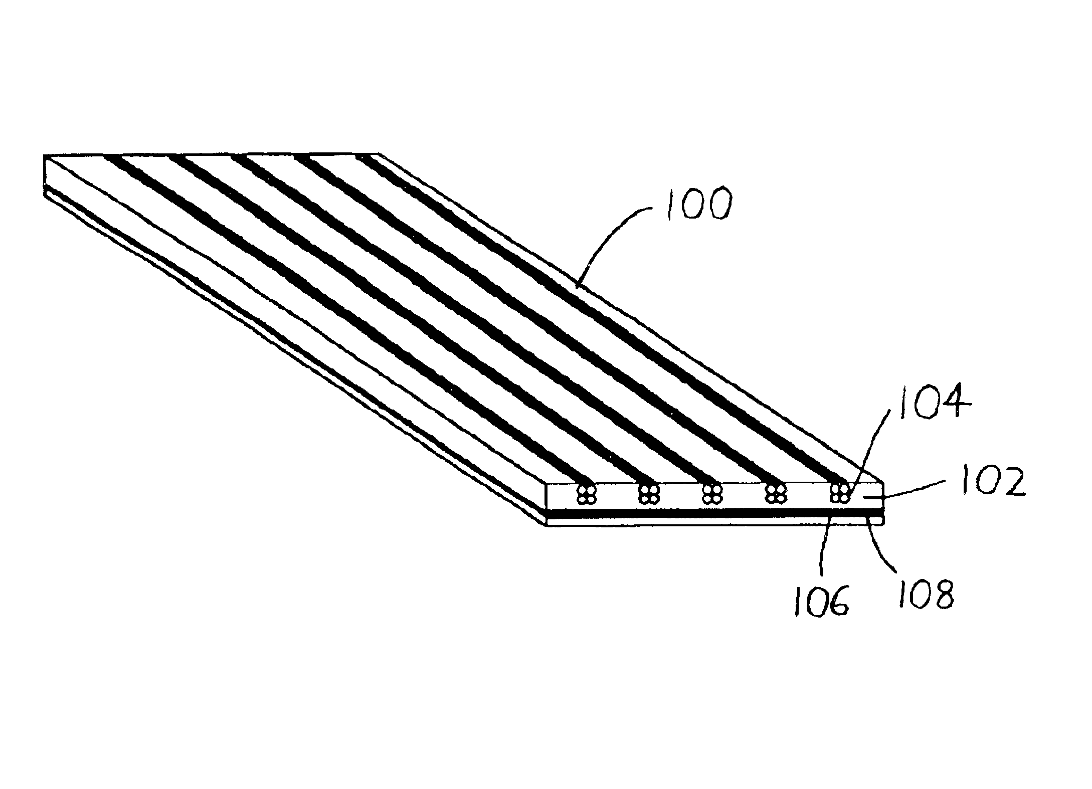
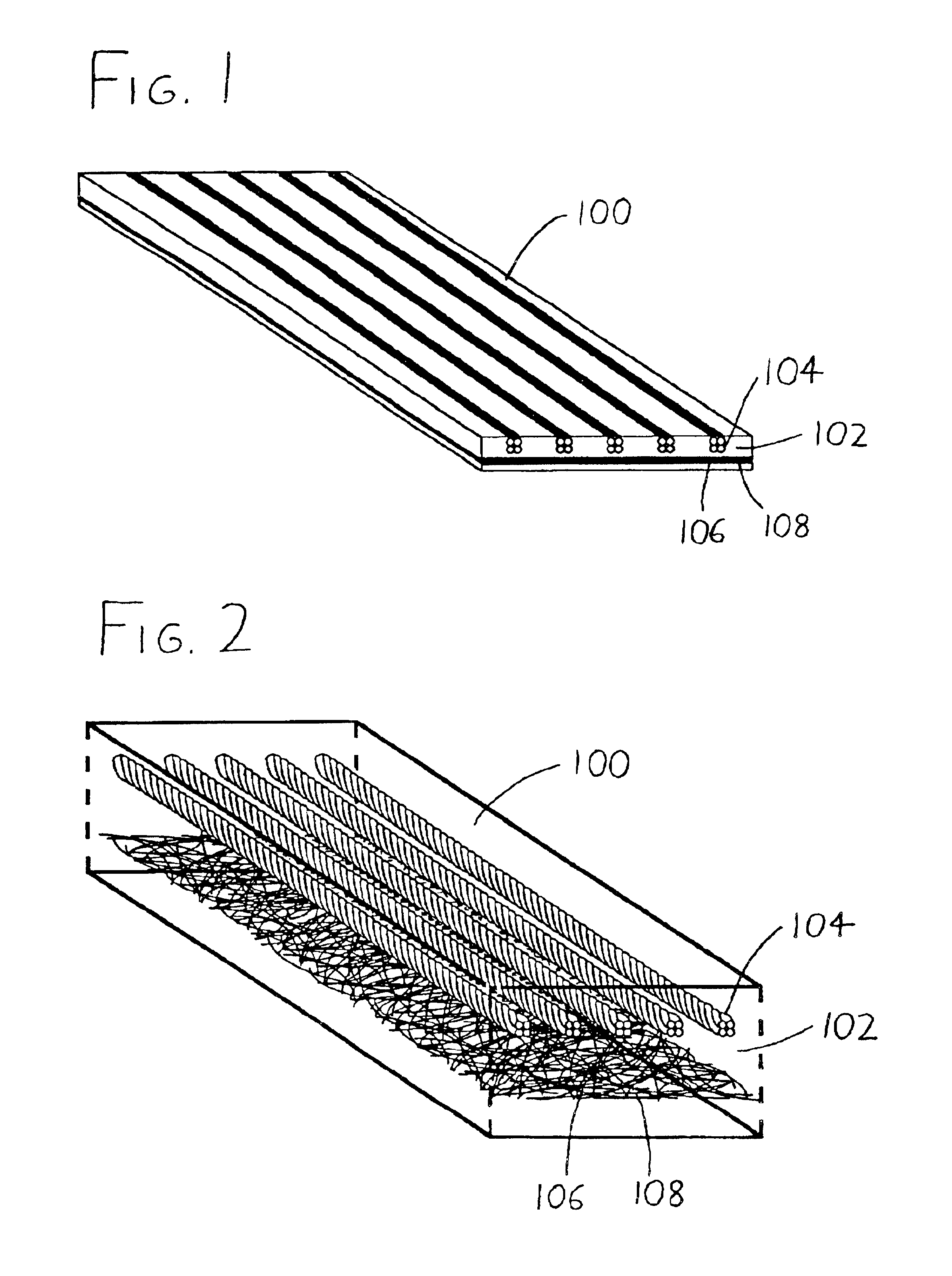
Referring to FIGS. 1 and 2, an exemplary preferred composite reinforcing strip 100 is illustrated. The strip 100, which is preferably continuously formed via pultrusion, includes a polymer matrix 102 having embedded fibers of two types. Initially, elongated continuous strand fibers 104, which are fed from reels during the pultrusion process, are provided with their lengths extending along the length of the strip 100, with the fibers 104 being transversely arrayed with their axes parallel to each other and to the axis of the strip 100. While the fibers 104 could be closely arrayed side by side with small spacings between the fibers 104 (e.g., with fiber spacings being some distance between 0-5.times. the fiber diameters), they are preferably provided with discrete spacings which are sufficiently large that a fastener (as discussed later in this document) can be accommodated between adjacent fibers if desired. More preferably, the fibers 104 are provided in bundles or rovings of multi...


PUM

PropertyMeasurementUnit
diameteraaaaaaaaaa
thickaaaaaaaaaa
thickaaaaaaaaaa

Abstract

A composite structural reinforcing strip is affixed to a structure to be reinforced (such as a bridge span, foundation pillar, or similar structure) by the use of several fasteners which extend through the strip and into the structure. The reinforcing strip preferably includes elongated continuous parallel fibers which have lengths extending along the length of the strip, and nondirectional fibers distributed transversely across the strip, with a polymer matrix affixing the parallel and nondirectional fibers. The strip may be placed on the structure to be reinforced, and may be attached thereon by actuating a common powder-actuated fastener gun to send fasteners through the strip and into the structure.

Description

This disclosure concerns an invention relating generally to post-construction reinforcement of structures (such as buildings, bridges, dams, and the like), and more specifically to structural reinforcements externally affixed to preexisting structures.In recent years there has been an increase in the use of lightweight, nonmetallic, fiber reinforced composite materials to repair and strengthen concrete structures. A common repair method is to adhesively bond strips of thin composite laminates, also known as fiber reinforced polymer (FRP) strips, to the surfaces of reinforced concrete beams or slabs to increase their capacity. Typically these composite strips are attached to the undersides of the beams / slabs to increase the flexural capacity of the reinforced concrete element. The method used to strengthen concrete beams with composite strips is similar to one that has been used with some popularity since the mid-1970's, particularly in Europe, to repair concrete beams with steel pla...

Claims


Application Information

Patent Timeline
Patent Type & Authority Patents(United States)
IPC IPC(8): E04G23/02E04C5/07
CPCE04C5/07E04G23/0218Y10T428/24074Y10T428/30Y10T428/24132Y10T428/24124E04G2023/0251E04G2023/0262Y10T428/249942Y10T428/249946Y10T428/24994
Inventor BANK, LAWRENCE C.LAMANNA, ANTHONY J.
Owner WISCONSIN ALUMNI RES FOUND
Learn More