
Hybrid inflator

a hybrid and inflator technology, applied in the field of inflators, can solve the problems of increased weight of oxygenated passengers, insufficient satisfaction of design requirements, and generation of fine particles harmful to passengers, and achieve the effect of high safety and compactness

Inactive Publication Date: 2004-10-26
DAICEL CHEM IND LTD
View PDF19 Cites 14 Cited by
  • Summary
  • Abstract
  • Description
  • Claims
  • Application Information

AI Technical Summary

Benefits of technology

An object of the present invention is to provide a hybrid inflator being made more compact and lighter without deteriorating a function as an inflator and guaranteeing a high safety, and an air bag apparatus using the same.
The hybrid inflator according to the present invention adjusts a molar ratio between an amount of pressurized medium and an amount of gas generated due to the combustion of the gas generating agent, and further adjusts a composition of the pressurized medium and the gas generating agent and / or improves a pressure resistance by using high strength steels, thereby making the inflator more compact and lighter than the conventional inflator.

Problems solved by technology

However, in the conventional hybrid inflator using a pressurized gas together with a solid gas generating agent, the design requirement mentioned above can not be sufficiently satisfied in some cases.
Further, in the case that the oxygen is contained in the pressurized gas, there is a problem such that the weight is increased by the oxygen.
In this case, however, there is a problem such that fine particles which are harmful to a passenger are generated due to the combustion of the gas generating agent.

Method used


Image

  • Hybrid inflator
  • Hybrid inflator
  • Hybrid inflator

Examples


example 1

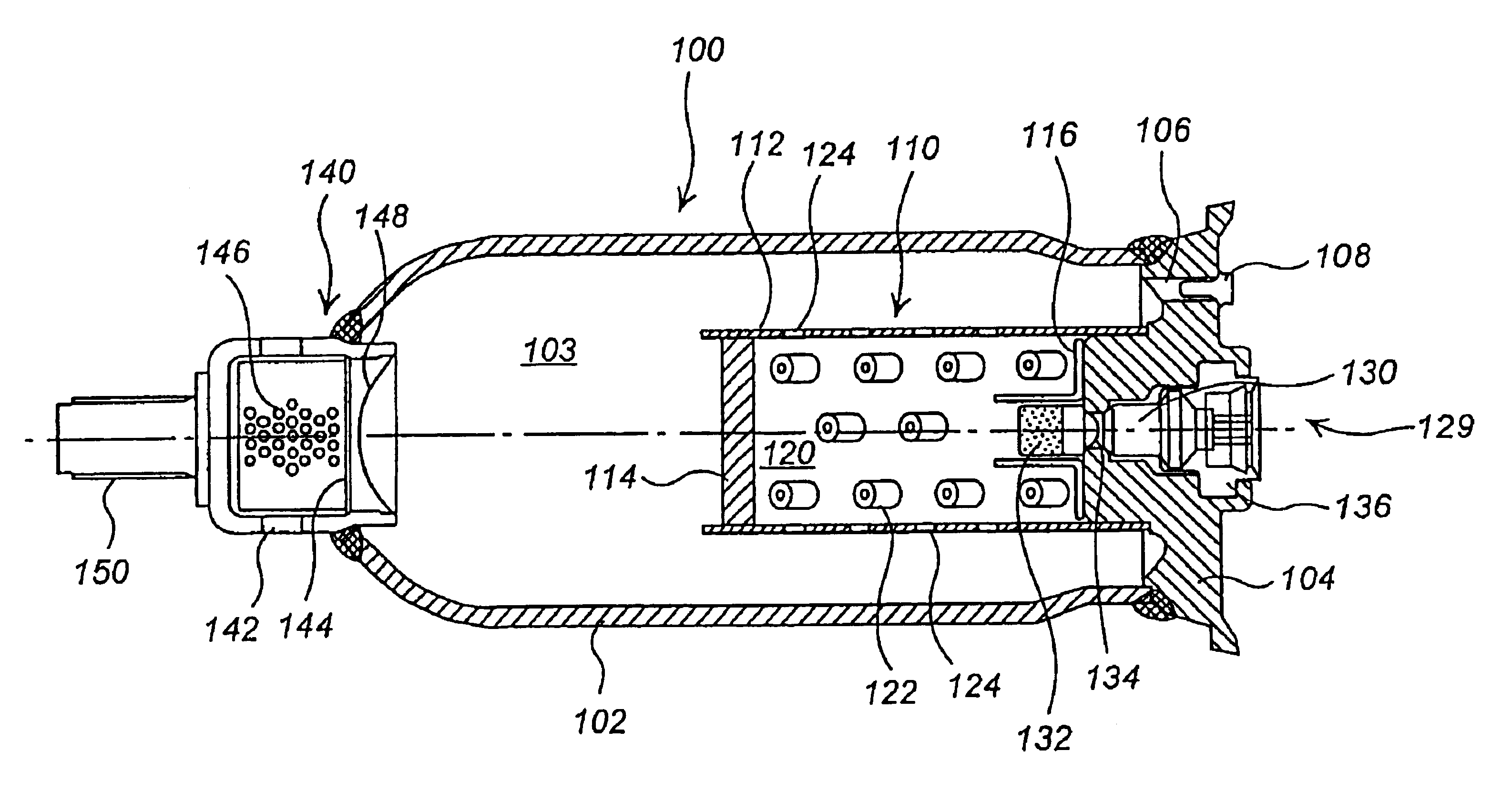
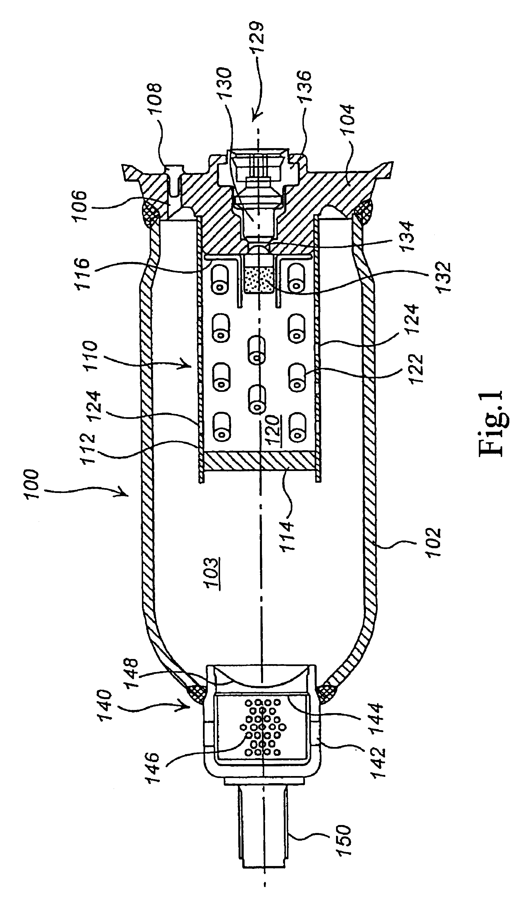
The hybrid inflator 100 in an aspect shown in FIG. 1 was manufactured. Details were as follows.

The inflator housing 102 was produced by using high strength steel (a tensile strength of 90 kg / mm.sup.2). The pressurized medium was 2.6 moles (100 g) of an argon and helium mixed gas (Ar:He=96:4 (molar ratio)) (internal pressure of 32000 kPa), and the gas generating agent was 40 g (corresponding to 1.0 moles of the generated gas) of a composition comprising nitroguanidine, strontium nitrate, carboxymethyl cellulose, and Japanese acid clay (34:50:9:7), at A / B=7.2 / 2.8. A weight ratio (a / b) between the pressurized medium and the gas generating agent was 2.5. Accordingly, 3.6 moles of gas could be totally utilized at the activation, and the total weight of the pressurized medium and the gas generating agent before the activation was 140 g. In this case, the pressure index (n) of the gas generating agent was 0.6.

The hybrid inflator 100 constituted by the structure mentioned above had the diam...

example 2

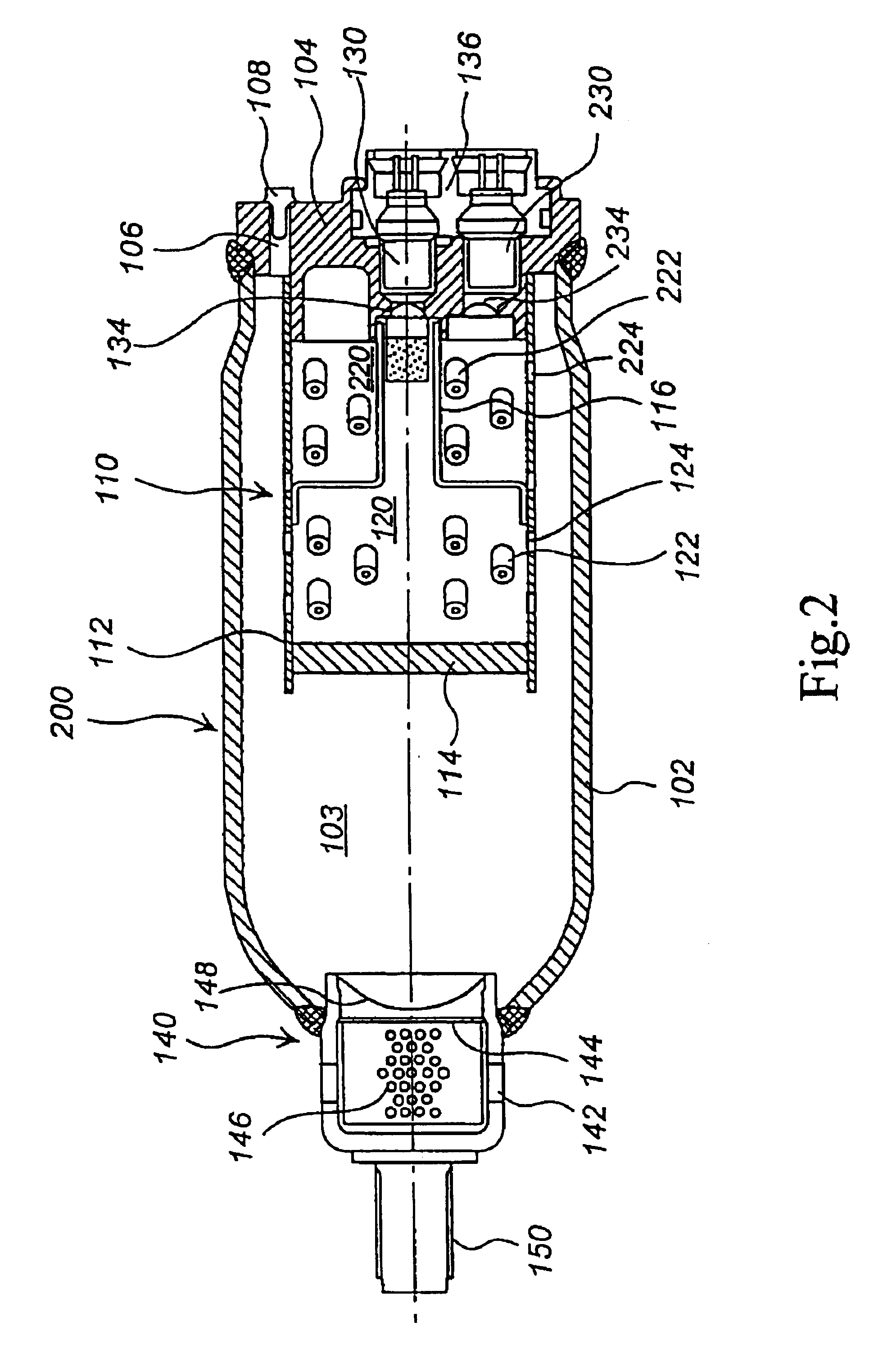
The hybrid inflator 100 having the same structure as that of the example 1 was manufactured. In this case, the internal capacity was set to 0.16 L and the capacity of the gas generator storing the gas generating agent was adjusted to store the amount of the used gas generating agent. The other constituting elements were as follows.

Pressurized medium: 1.6 moles (62 g) of mixed gas of argon and helium (Ar:He=96:4 (molar ratio)) (the internal pressure 32,000 kPa)

Gas generating agent: 80 g (the generated gas of 2.0 moles) of the same agent as that of the Example 1

A / B: 1.6 / 2.0

A / b: 62 / 80=0.775

Total gas amount at a time of activating: 3.6 moles

As a result of activating the hybrid inflator, the internal pressure was 68,000 kPa.

example 3

The hybrid inflator was manufactured in the same manner as that of the example 2 except that the gas generator was composed of a pressure resisting container and the gas generating chamber in which the gas generating agent had been stored was set to the normal pressure. In this case, in order to keep the gas generating chamber at the normal pressure, the rupturable disk was provided between the gas generating chamber and the inflator housing. As a result of activating such a hybrid inflator, substantially the same result as that of the example 2 could be obtained.


PUM

PropertyMeasurementUnit
pressureaaaaaaaaaa
pressureaaaaaaaaaa
outer diameteraaaaaaaaaa

Abstract

A hybrid inflator which is made more compact and lighter is provided. An excessive internal pressure increase at a time of activation is prevented by setting a molar ratio (A / B) between a pressurized medium (A moles) charged in a housing 102 and an amount of a gas (B moles) generated due to combustion of a gas generating agent 122 to 8 / 2 to 1 / 9.

Description

The present invention relates to an inflating-type safety system of motor vehicles, and more particularly to a hybrid inflator capable of inflating an air bag rapidly and being made more compact and lighter, and an air bag apparatus using the same inflator.PRIOR ARTWith the development of an inflator for an inflating-type safety system of motor vehicles, a hybrid inflator using both a pressurized gas and a solid gas generating agent is attracting attention. A main design requirement for the hybrid inflator is that the inflator inflates an air bag by a predetermined volume in a predetermined time so that the air bag is effectively activated. Various proposals concerning a structure to meet the requirement have heretofore been made. As the prior arts, there have been known JP-A No. 8-282427, EP No. 0844148, U.S. Pat. Nos. 5,351,988, 5,882,036, 5,851,027, 3,868,124 and 3,758,131, etc.Further, since the hybrid inflator is manufactured to be installed in the motor vehicle, the weight of ...

Claims


Application Information

Patent Timeline
Patent Type & Authority Patents(United States)
IPC IPC(8): B60R21/26C06D5/00C06D5/06B01J7/00B60R21/268B60R21/217B60R21/272C06B43/00
CPCB60R21/272C06D5/06C06D5/00B60R2021/2633B60R21/268B60R21/26B60R21/217
Inventor KATSUDA, NOBUYUKIHIRATA, NORIMASAYAMAZAKI, MASAYUKI
Owner DAICEL CHEM IND LTD
Learn More