
Position encoder using statistically biased pseudorandom sequence

a pseudorandom sequence and encoder technology, applied in the field of position sensors, can solve the problems of degrading the quality of the image to be processed, affecting so as to achieve the effect of increasing the accuracy of absolute position measuremen

Inactive Publication Date: 2004-09-07
BISHOP INNOVATION PTY LTD
View PDF3 Cites 18 Cited by
  • Summary
  • Abstract
  • Description
  • Claims
  • Application Information

AI Technical Summary

Benefits of technology

This approach enables high-accuracy absolute position measurement with improved resolution and reduced susceptibility to mechanical manufacturing tolerances, achieving fine resolution position measurement with a single detector array and minimizing errors from non-homogeneous illumination and pixel imperfections.

Problems solved by technology

Such absolute position sensors generally do not provide the position measurement accuracy provided by incremental sensors as they cannot use the aforementioned quadrature interpolation techniques.
The use of a barcode consisting of varying bar widths for coarse absolute position measurement is known to have difficulties in image processing due to the width interpretation of the barcodes due to imperfections of the individual pixels that make up the detectors in the array, and the variations in the quality of the barcode markings.
Also, as the sensor requires a finite time to integrate an image, movement of the barcode relative to the sensor during this time period produces smearing of the image, further degrading the quality of the image to be processed.
A further problem is the variation of the image signal produced on the array.
The evaluation of the binary states of all of the bits incident on the array by the use of a single image threshold level is susceptible to error because the image levels on the array are due, not only to the barcode pattern, but also the effects of non-homogeneous illumination, non-homogenous surface properties, and the combination of the positioning of all the components that transmit, reflect or repropogate, and collect the EMR.

Method used


Image

  • Position encoder using statistically biased pseudorandom sequence
  • Position encoder using statistically biased pseudorandom sequence
  • Position encoder using statistically biased pseudorandom sequence

Examples


Embodiment Construction

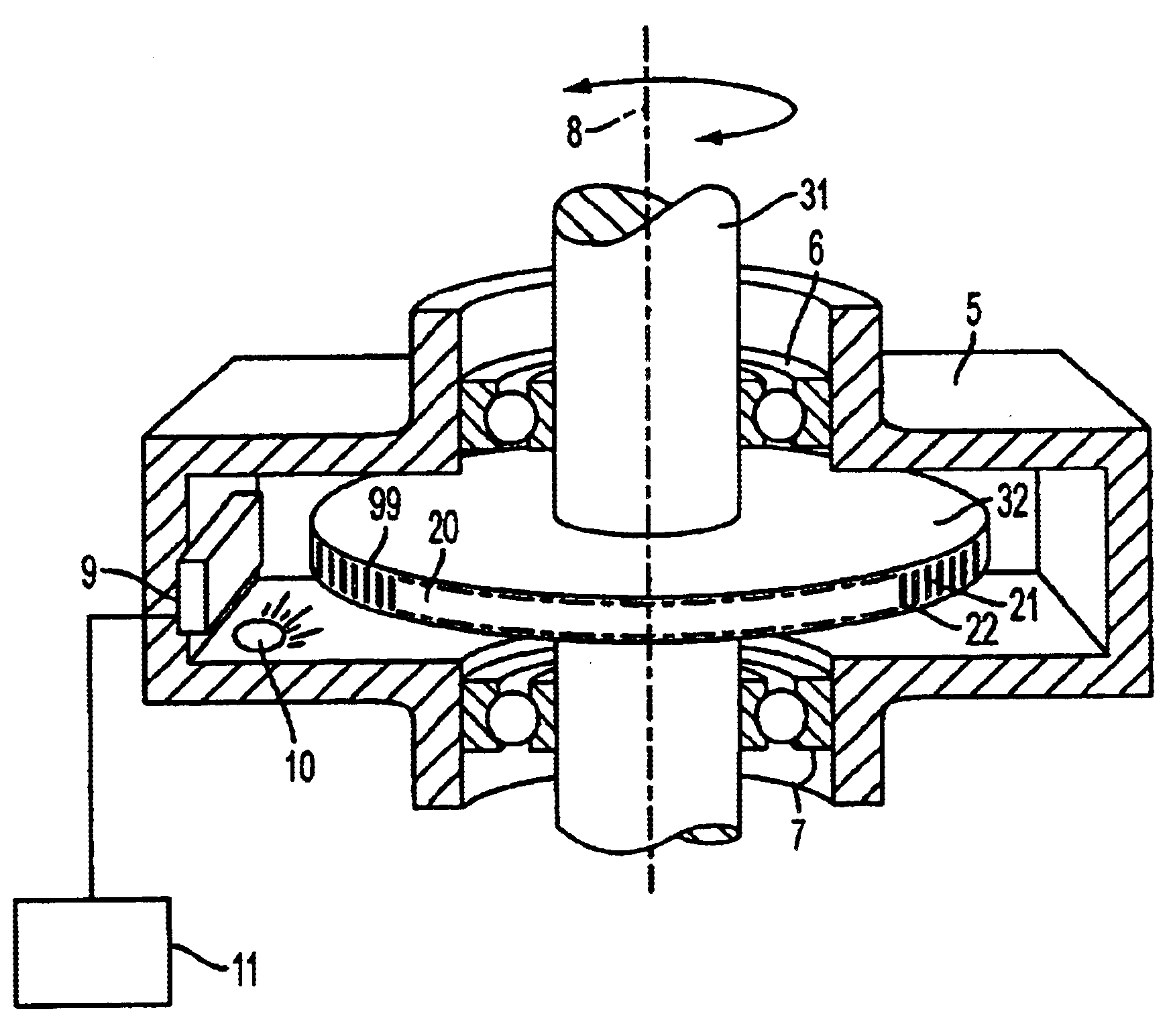
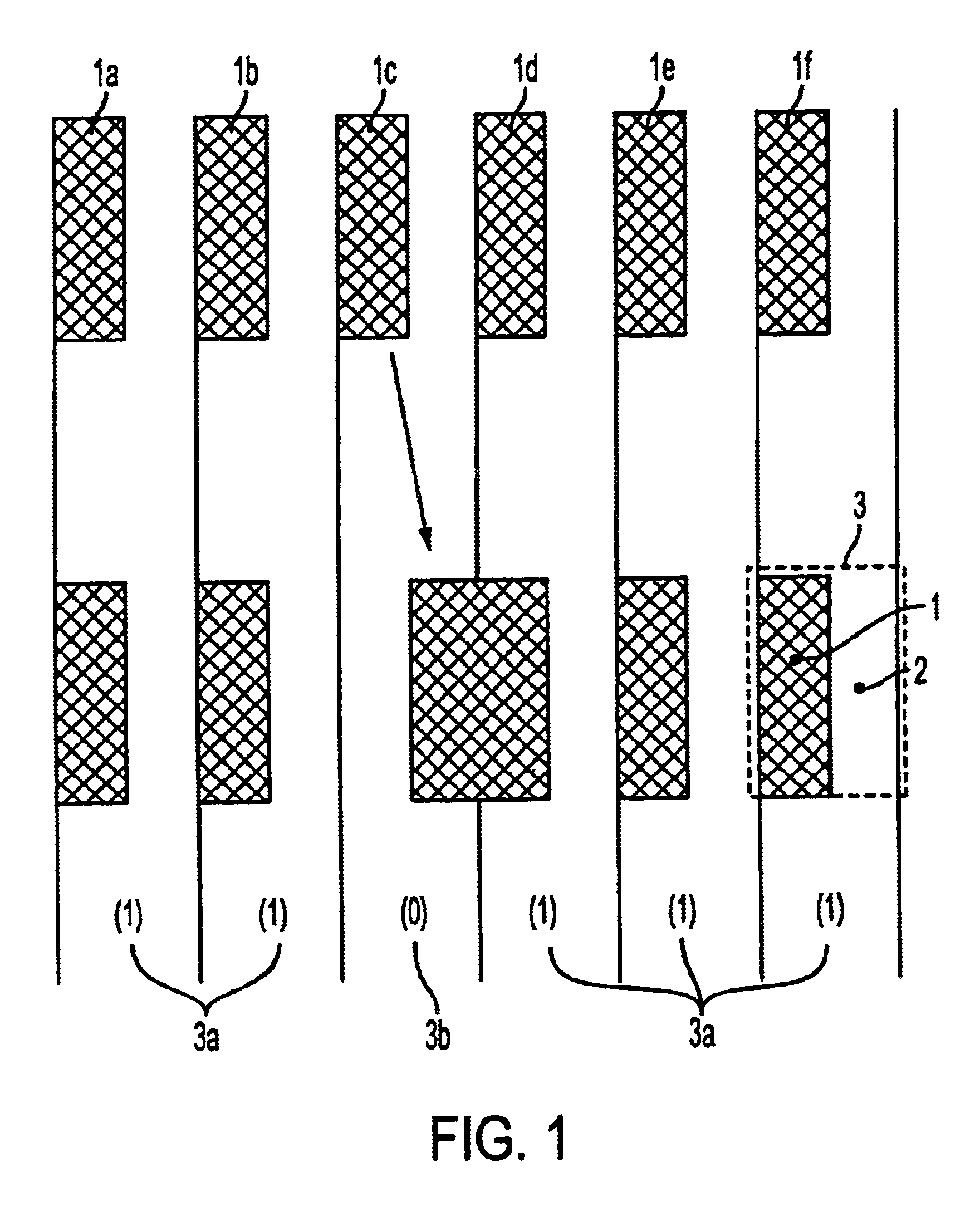
FIG. 1 depicts how a 50% regular duty cycle coding pattern containing bars 1a-f can be modified to a Manchester code by moving one bar 1c in the pattern. The Manchester code can be disposed upon a surface such that bars 1 are of constant thickness and extend in a direction perpendicular to the intended direction of positional measurement of the barcode. The coding pattern is shown as viewed by a known array of detectors (not shown). Each bar 1 and its adjacent space 2 define a single bit 3.

The Manchester code is formed by a consecutive sequence of bits 3. In each bit 3, bar 1 comprises of a region of low reflectivity or transmissibility and adjacent space 2 is of a region of high reflectivity or transmissibility. Over the whole of the Manchester code comprising 6 bits, one regressive bit 3b is of binary state (0). The remaining five dominant bits 3a are of binary state (1).

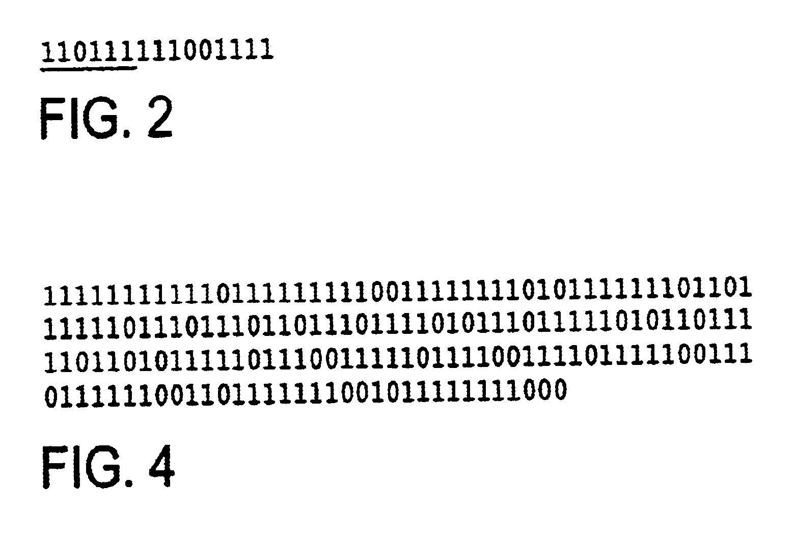
FIG. 2 depicts a sequence of 15 bits, of which 12 bits are dominant bits of binary state (1), and of which 3 bi...


PUM


Abstract

A position sensor encodes absolute position via n consecutive members of a pseudorandom sequence of bits, where each bit (30a-30k) comprises a region of high transmission or reflectivity adjacent to a region of low transmission or reflectivity. The pseudorandom sequence is chosen such that every series of n consecutive bits (30a-30k) in the sequence is predominantly formed from a predetermined bit value (1 or 0). The light transmitted or reflected from the series is therefore detected as a substantially periodic intensity pattern (42), which can be processed via Fourier analysis to yield an accurate interpolation of relative position. An example is given of a pseudorandom sequence, which can be represented as a cyclic Manchester code, in which at least 8 members of every series of 11 consecutive bits has a bit value of 1.

Description

This invention relates to a position sensor for the sensing of the absolute position of a movable body without requiring counting from a reference mark. In particular the invention relates to a barcode system where a linear array of detectors is used to read and process the absolute position of a surface to which the barcode is attached to high accuracy. The barcode is coded with values that are used to find the absolute position of the barcode marking within the length of the barcode, and has the ability to be interpolated to provide a resolution of measurement better than that of the barcode marking (or spacing) pitch, or indeed better than that of the individual detector pitch of the linear array of detectors.Conventionally, position sensors have been used for sensing the position of a body that is movable relative to the sensor. These sensors typically consist of a detector unit and a graduated scale of material with contrasting bars formed of alternating transparent and opaque ...

Claims


Application Information

Patent Timeline
Patent Type & Authority Patents(United States)
IPC IPC(8): G01D5/12G01D5/249G01D5/26G01D5/347H03M1/22H03M1/28
CPCG01D5/2454G01D5/2495G01D5/3473G01D5/34792H03M1/282
Inventor BOYTON, DESMOND BRUCE
Owner BISHOP INNOVATION PTY LTD
Learn More