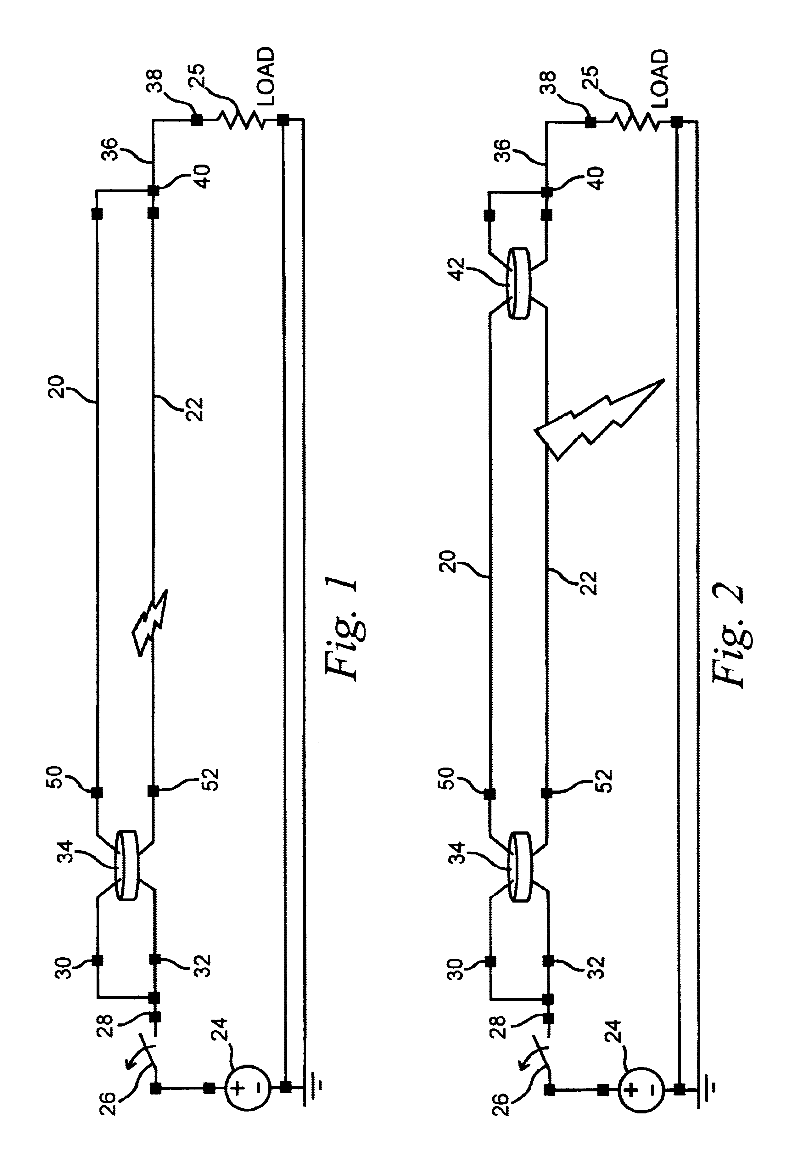
A ground fault trip condition is created by an imbalance of currents flowing between a line conductor and a neutral conductor which could be caused by a leakage current or an arcing fault to ground.
However, arcing faults may not cause a conventional
circuit breaker to trip.
There are many conditions that may cause an arcing fault.
For example, corroded, worn or aged wiring, connectors, contacts or insulation, loose connections, damaged wiring, and electrical stress caused by repeated overloading,
lightning strikes, etc.
These faults may damage the conductor insulation and cause the conductor to reach an unacceptable temperature.
Standard
overcurrent devices used in circuit breakers respond to the
heating effect of current in a resistive wire to "thermal trip" the breaker, but these do not respond to the
sputtering arc currents which cause intense arc heating and fire.
Until recently, such arc detection capability has not been available in circuit breakers or relays.
Arc detection has been available for 60 Hz residential, commercial or
industrial systems, but has not heretofore been resolved for aircraft wiring systems.
In addition, most aircraft circuits do not have the neutral return conductor found in 60 Hz systems.
Arcing fault detection is not provided by these devices.
Aircraft arc detection is not possible using arc detectors designed for 60 Hz circuits for several reasons.
For example, 60 Hz arc detectors partly respond to ground fault which is not possible on standard aircraft
branch circuits.
Also, the methods used at 60 Hz cannot be automatically extended to cover a
power frequency range as high as 400 Hz, typically used in aircraft.
Advancements in electrical
circuit protection introduced by the residential and commercial industries have been slow finding their way into
aerospace applications.
Under ideal conditions, GFCI can detect phase to ground arcs as low as six milliamps, but cannot detect series arcs or improve line to neutral fault trip times.
During arcing faults these currents are often small, short in duration and well below the
overcurrent-time protection curve designed into these breakers.
In many aircraft circuits, the neutral conductor is not available to complete the necessary ground fault detection circuit and GFCI protection is not possible.
Occasionally, however, the arc blows apart the faulted components creating a larger
arc voltage and reducing the fault current below the trip curve and causing "ticking faults."
The
average current may not be sufficient to trip a conventional breaker by heating the
bimetal strip or the
peak current may not be large enough to trigger the magnetic trip latch.
Unfortunately, the fault current can be limited by a circuit with too much impedance to immediately trip the thermal-magnetic breaker.
Parallel arcing is generally more hazardous than series arcing.
The energy released in the arc is much higher with temperatures often in excess of 10,000 Deg. F. This causes pyrolyzation or
charring of the insulation, creating conductive carbon paths and ejecting hot
metal that is likely to encounter flammable materials.
Series arcing typically begins with
corrosion in pin-socket connections or loose connections in series with the electrical loads.
Since the
peak current is typically never greater than the
design load current, series arcing is much more difficult to detect than parallel arcing.
These arcs cause load
voltage drops and heating of the wire, plug pin, or terminal lug.
This heating can lead to component failure and ignition source.
Nuisance
tripping is not acceptable as several systems may be powered by one breaker.
Summarizing briefly, heat, arcs or electrical ignition are often caused by loose connections, broken or shorted wires in the power
distribution system.
In aircraft wiring, vibration,
moisture temperature extremes, improper maintenance and repair all contribute to wiring failure.
This leads to arcing and may ignite combustible components.
Furthermore, carbon tracking caused by heat generated by the arc can deteriorate the wire insulation, exposing the conductors and resulting in intermittent short circuits between individual wires.
These inter-wire shorts can cause damage to delicate
avionics and cause
system malfunctions in-flight.
Ground fault detection has not been an option on
single phase aircraft circuits due to the use of the aircraft frame to return
neutral current.
Neutral conductors on an aircraft would add significant weight to an aircraft and thus typical ground fault sensing is not possible.
Neutral conductors are rarely employed to save weight.
In the prior art of detecting arcing faults, complex algorithms have been necessary to distinguish
normal load current transients from arcing faults.
Unfortunately ground fault detection is not available in most aircraft circuits as weight considerations and minimizing wire weight is a primary design goal.
Any faults in the power wire will likely breach the insulation and produce currents in the sensor wire which are detected by a special circuit which trips the breaker.
The
disadvantage to this
system is the added weight and complexity of the shield wire and the possibility that the shield may become disconnected at some point, unbeknownst to the sensor circuit.


