The features, nature, and advantages of the present invention will become more apparent from the detailed description set forth below when
FIGS. 1A through 1C are diagrams respectively illustrating FDM, TDM, and CDM techniques to provide multiple types of service for a number of remote terminals in a
wireless communication system;
FIGS. 2A and 2B are plots of the transmit power from a
base station in a CDM system for a number of voice / data users and for a number of voice / data and packet data users, respectively;
FIG. 3 is a diagram of a frame format and a slot format for a dedicated physical channel as defined by the W-CDMA standard;
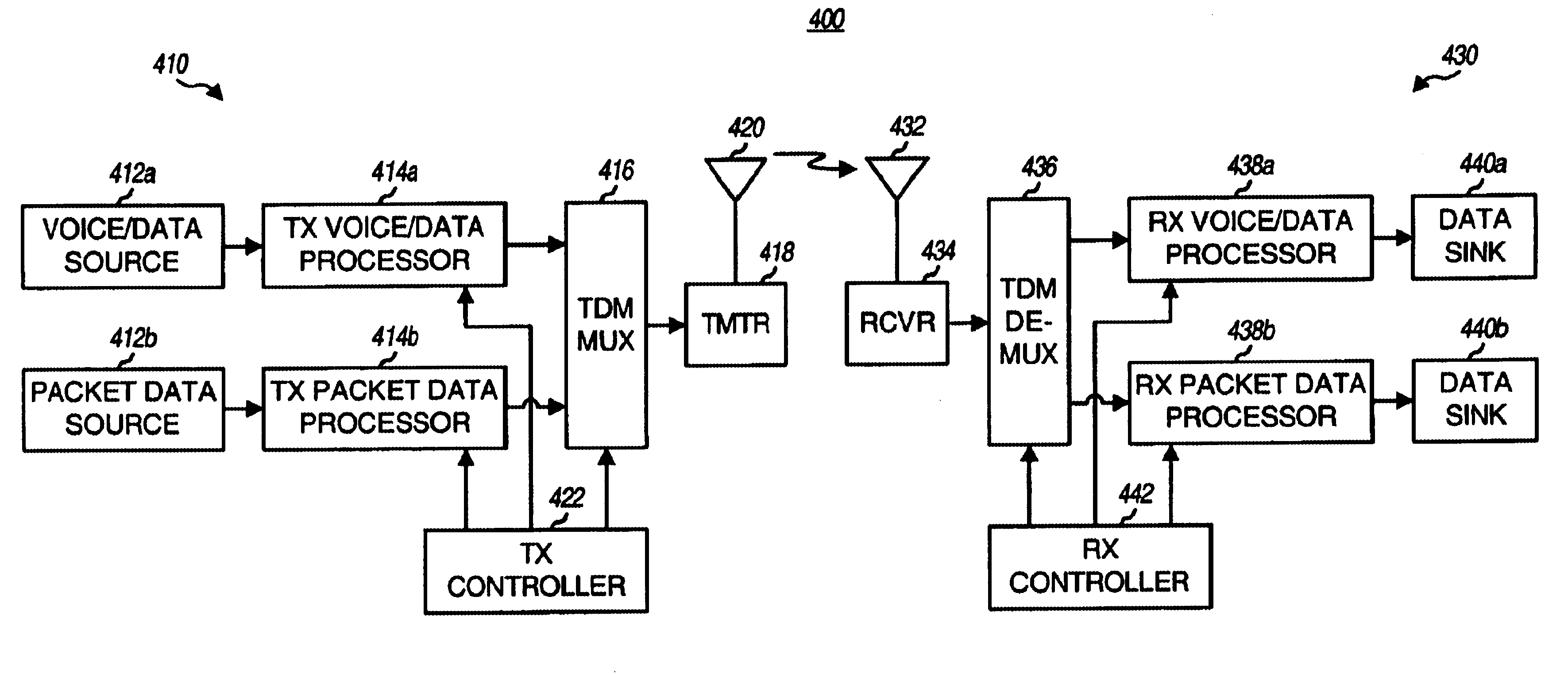
FIG. 4 is a simplified
block diagram of a communication system that can implement various aspects of the invention;
FIG. 5 is a plot of the transmit power for a number of voice / data transmissions and a number of packet data transmissions from a particular
base station;
FIGS. 1A through 1C are diagrams illustrating three different techniques to provide multiple types of service for a number of remote terminals in a
wireless communication system. Some of these different types of service may include, for example, voice, packet data, video, broadcast, messaging, and so on. Other overhead transmissions typically employed for a wireless communication system may include, for example,
paging,
pilot,
control channel, and so on. For simplicity, high-speed packet data is referred to herein as simply "packet data," and remaining types of data (e.g., voice, overhead, certain types of medium and low rate data,
delay sensitive data, and others) are collectively referred to as "voice / data." Optimization of packet data transmission is an important aspect of efficient spectrum utilization. However, minimizing the
impact of packet data transmission on voice / data transmission is also important to maintain the desired
level of service quality and reliability.
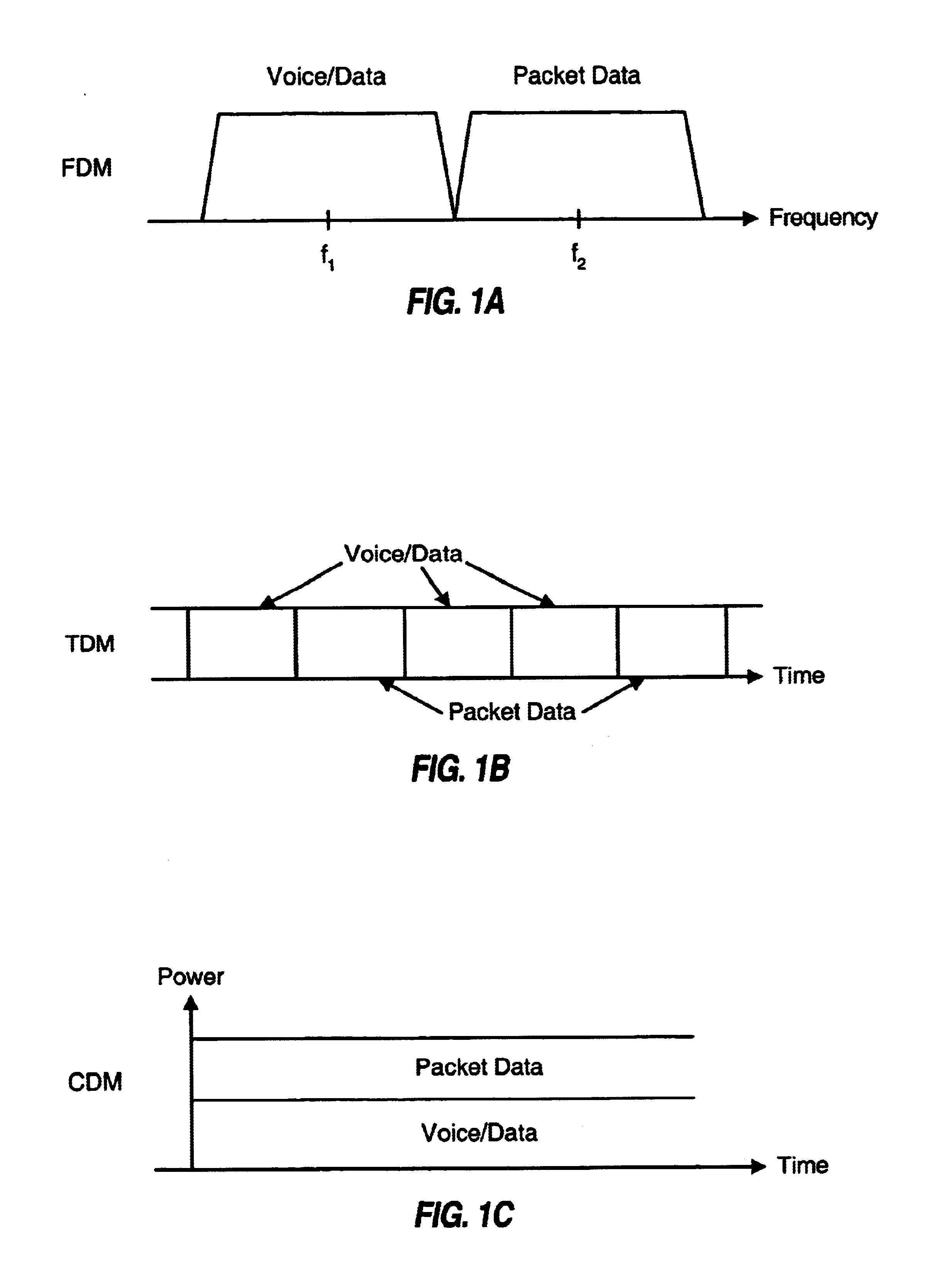
FIG. 1A shows a frequency division
multiplex (FDM) system that supports voice / data and packet data services using two frequency bands, f1 and f2. As noted above, because of the differences in the characteristics and requirements of voice / data and packet data services, it is typically preferable to segregate these services. In the FDM system, voice / data service can be supported by a first system (e.g., an IS-95 system) with one
carrier signal at a first frequency, and packet data service can be supported by a second system (e.g., an HDR system) with a second
carrier signal at a second frequency.
FIG. 1B shows a time division
multiplex (TDM) system in which transmissions occur over discrete time units, which may be referred to as "slots" in some systems or "frames" in some other systems. For the TDM system, a number of slots are allocated to support voice / data service and remaining slots are used to support packet data service. Once such TDM system is a
Global System for Mobile Communications (
GSM)+Generalized
Packet Radio System (GPRS) system. GPRS provides
GSM packet data service.
FIG. 1C shows a code division
multiplex (CDM) system in which voice / data and packet data services share the available transmit power. For the CDM system, each voice / data transmission and each packet data transmission is typically
channelized by a respective channelization code such that the transmissions are (ideally) orthogonal to each other. The transmit power for each transmission may be adjusted to maintain the desired level of performance. The number of transmissions that can be concurrently supported and the
data rate of each transmission are dictated by the data loads, the available transmit power, and other factors.
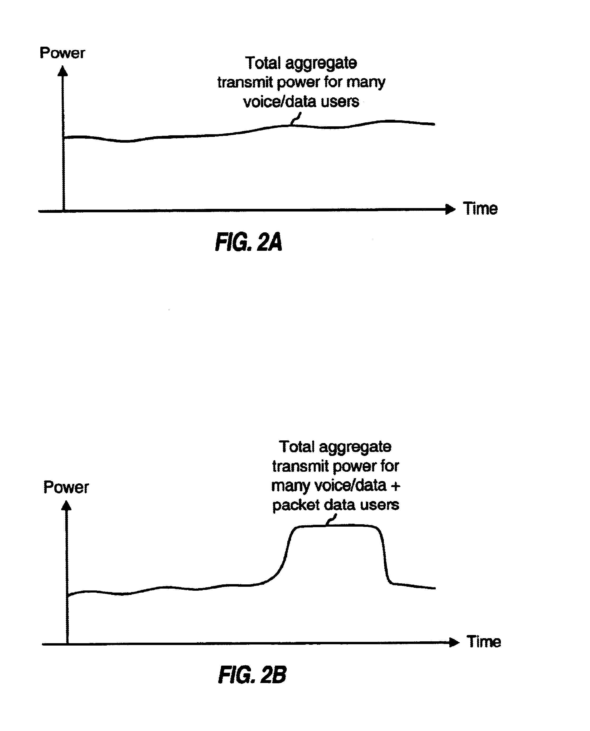
FIG. 2A is a plot of the transmit power from a base
station in a CDM system that supports a number of voice / data users concurrently. For this CDM system, the transmit power to each individual user may vary widely due to changes in the
data rate and path conditions. However, the total aggregate transmit power for all voice / data users typically varies over a smaller range (percentage wise) due to statistical averaging. Since each voice / data user typically requires only a medium to
low data rate, a number of voice / data users can be supported concurrently. As the number of voice / data users increases, the statistical averaging improves and the amount of variation in the total aggregate transmit power decreases.
For a wireless communication system, the transmit power from each transmission source (e.g., each base
station) acts as interference to other transmitting sources when they use the same radio resources. For the CDM system, the quality of the signal received by each user is dependent on the total
noise and interference experienced by the signal received by the user. Thus, to maintain the desired
signal quality, it is desirable that the interference remains as low as possible and as constant as possible (the system can generally compensate for
progressive change in the interference but not for sudden changes).
FIG. 2B is a plot of the transmit power from a base
station in a CDM system that supports a number of voice / data and packet data users concurrently. Because of the bursty nature of packet data service and because of the
high peak rate that can be used for packet data transmission, the total aggregate transmit power for voice / data and packet data users can vary over a much greater range over a shorter period of time than when transmitting to only voice / data users. This can be observed by comparing the plot in FIG. 2B with the plot in FIG. 2A. The larger variation in the total transmit power from the base station can cause a larger fluctuation in the
signal quality of the transmissions from other base stations, which may result in performance degradation for these transmissions. Moreover, the larger variation in the total transmit power can also cause a larger fluctuation in the
signal quality in the transmissions from this transmitting base station due to multipath and other phenomena.
The disclosed method and apparatus provide various techniques that can be used to support voice / data and packet data services concurrently and to minimize the
impact of packet data service on voice / data service. In accordance with one embodiment, voice / data and packet data can be multiplexed within a transmission interval (e.g., a slot) such that the available resources are efficiently utilized. In accordance with another embodiment, the transmit power from a base station is controlled such that the amount of variation in the total transmit power is maintained within a particular range to reduce degradation to transmissions from this and other base stations.
In many CDM systems, data is transmitted over discrete transmission intervals. The duration of the transmission interval is typically defined to provide good performance for the service(s) being supported by the CDM system. For example, for the W-CDMA system, a transmission occurs over 10 msec radio frames, with each radio frame being further divided into 15 slots. The data to be transmitted is partitioned, processed, and transmitted in the defined transmission interval.
In accordance with one embodiment, a portion of the transmission interval (i.e., a voice / data partition) can be allocated for voice / data transmission and the remaining portion of the transmission interval (i.e., a packet data partition) can be used for high-speed packet data transmission. The voice / data and packet data partitions can be dynamically defined based on the voice / data load and the packet data load, and can be effectuated through proper signaling, as described in further detail below. The partitioning of the transmission interval into voice / data and packet data partitions can be achieved for various CDM systems such as, for example, the W-CDMA system, the cdma2000 system, and other systems. For a better understanding, the partitioning of the transmission interval is now specifically described for the
downlink transmission in the W-CDMA system.
FIG. 3 is a diagram of a frame format and a slot format for a dedicated physical channel as defined by the W-CDMA standard. A different frame format is defined by the W-CDMA standard for each type of physical channel such as the downlink dedicated channel (DPCH), the downlink shared channel (DSCH), and so on. The data to be transmitted on each physical channel (i.e., the traffic data) is partitioned into radio frames, with each radio frame covering a 10 msec time period and including 15 slots labeled as slot 0 through slot 14. Each slot is further partitioned into one or more fields used to carry a combination of traffic data, overhead data, and
pilot data.
As shown in FIG. 3, for the dedicated physical channel, a slot 310 includes a first data (Data1) field 320a, a second data (Data2) field 320b, a transmit
power control (TPC) field 322, a
transport format combination indicator (TFCI) field 324, and a
pilot field 326. Data fields 320a and 320b are used to send traffic data (e.g., voice, packet data, messaging, or others) for the dedicated physical channel. Transmit
power control field 322 is used to send
power control information to direct the remote terminal to adjust its transmit power on the uplink either up or down to achieve the desired level of performance while minimizing interference to other remote terminals.
Transport format combination indicator field 324 is used to send information indicative of the format (e.g., the
bit rate, channelization code, and so on) of the dedicated physical channel as well as of a shared physical channel associated with the dedicated physical channel.
Pilot field 326 is used to send pilot data for the dedicated physical channel.
Table 1 lists some of the slot formats defined by the W-CDMA standard (version V3.1.1) for the dedicated physical channel. Each slot format in Table 1 defines the length (in number of bits) of each field in the slot. As shown in Table 1, the
bit rate of the dedicated physical channel can vary over a
large range of values (e.g., from 15 Kbps to 1920 Kbps) and the number of bits in each slot varies correspondingly. One or more fields in the slot may be omitted (i.e., length=0) for some of the slot formats.
In accordance with the W-CDMA standard, a number of physical channels can be used to send data to a particular remote terminal. Each physical channel is
channelized with an orthogonal variable
spreading factor (OVSF) code having a particular
spreading factor (
ranging from 4 to 512 for the downlink). The OVSF code channelizes the physical channel such that the transmission on this physical channel is orthogonal to other transmissions on other physical channels. The OVSF code is akin to the Walsh code used in the IS-95 system to channelize the forward link transmissions. The OVSF code for each physical channel is typically determined (by the network) at the start of a communication session and typically does not change during the session.
The
spreading factor corresponds to the length of the OVSF code. A smaller spreading factor (e.g., 4) corresponds to a shorter code length and is used for a higher
data rate, and a larger spreading factor (e.g., 512) corresponds to a longer code length and is used for a lower data rate. As shown in Table 1, the total number of bits per slot (and thus the total number of bits available for traffic data) varies over a wide range and is dependent on the spreading factor used for the slot.
In accordance with one embodiment, data fields 320a and 320b allocated for traffic data in each slot can be partitioned into a voice / data partition and a packet data partition. The voice / data partition can be used for the voice / data to be transmitted in the slot. The packet data partition can be used to transmit packet data.
For a particular voice / data transmission on the physical channel, the
data bits for the transmission are segmented and processed, as described in further detail below. In accordance with the W-CDMA standard, the voice / data
payload for each slot can include any number of
data bits (i.e., does not need to be a specific number of bits). Also, the size of the voice / data
payload can vary from slot to slot. Depending on the number of bits in the
payload, the spreading factor of the OVSF code can be selected accordingly.
As shown in Table 1, the spreading factor for the OVSF code ranges from 4 to 512 and in powers of two. Each spreading factor and slot format is associated with a particular number of
data bits that can be transmitted in a slot. The spreading factor can thus be used to (coarsely) select the capacity of the slot. Typically, for a given payload size, the largest possible spreading factor that approximately matches that payload size is selected.
The number of coded bits in the payload for a slot may not be equal to the number of available data bits for the selected spreading factor. The W-CDMA standard thus defines a rate-matching scheme whereby a number of coded bits in the payload can be punctured (i.e., deleted) or repeated such that the number of rate-matched bits is equal to the number of available bits in the slot.
Using the processing mechanism defined by the W-CDMA standard (e.g., the spreading), the capacity of a slot can be defined. A portion of the slot capacity can be used for voice / data and the remaining portion can be used for packet data. A "slot partition parameter" can be defined and used to identify the particular allocation (e.g., a percentage amount) of the available slot for packet data and voice / data. The slot partition parameter may denote full allocation of the slot for voice / data (e.g., slot partition parameter=0%), or full allocation of the slot for packet data (e.g., slot partition parameter=100%), or any possible percentage and mix in between those two extremes.
Table 2 lists the partitioning of a slot for voice / data and packet data for three different sets of spreading factors. For a given voice / data payload, the spreading factor can be selected such that the slot capacity approximately matches the payload. Depending on the particular payload size, different spreading factors may be required, as shown in the second column. If the spreading factor is then decreased by a factor of two, the slot capacity is approximately doubled, as shown in Table 1. In this case, half of the slot capacity can be allocated for the voice / data payload and the other half of the slot capacity can be used for packet data, as shown in the third column. Thus, if the spreading factor is decreased by a factor of two, approximately 50% of the slot capacity can be used for packet data (i.e., the slot partition parameter=50%).
Similarly, if the spreading factor is decreased by a factor of four, the slot capacity is approximately quadrupled. A quarter of the slot capacity can then be allocated for the voice / data payload and the other three-quarter of the slot capacity can be used for packet data, as shown in the fourth column. Thus, if the spreading factor is decreased by a factor of four, approximately 75% of the slot capacity can be used for packet data (i.e., the slot partition parameter=75%). The spreading factor can be further reduced to further increase the slot capacity and slot partition parameter.
As shown in Table 1, the spreading factor has lengths of powers of two and the slot capacity approximately doubles each time the spreading factor is reduced by a factor of two. This coarse increment in the spreading factor results in a correspondingly coarse increment in the slot partition parameter (e.g., 0%, 50%, 75%, and so on, up to 100%). Fine adjustment of the slot partition parameter can be achieved by use of the rate-matching mechanism defined by the W-CDMA system. With the rate-matching, the slot partition parameter may be defined to be any particular value (e.g., 20%, 30%, and so on). The voice / data payload can then be fitted into the voice / data partition by selecting the proper rate-matching parameters, as described in further detail below. The rate-matching can thus be used for fine adjustment of the slot partition parameter.
