Mobile terminal and method of providing a network-to-network connection
a mobile terminal and network connection technology, applied in the field of telecommunication systems, can solve the problems of inability of the network to handle, inability of the pdn to associate with the te, and inability to provide the network connection
- Summary
- Abstract
- Description
- Claims
- Application Information
AI Technical Summary
Problems solved by technology
Method used
Image
Examples
first embodiment
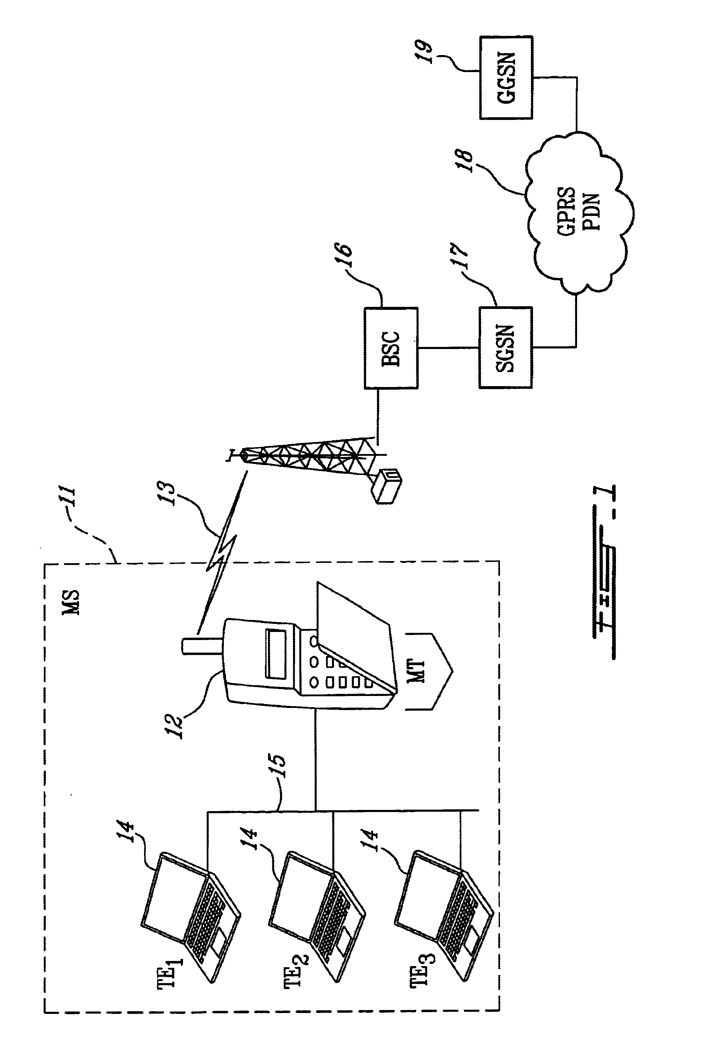
FIG. 1 is a simplified block diagram of a network architecture suitable for implementing the method of the present invention. The exemplary architecture illustrated in FIG. 1 is for a GPRS network, although, in the first embodiment, the invention may be utilized with any type of wireless PDN. In the GPRS network architecture, a Mobile Station (MS) 11 includes a Mobile Terminal (MT) 12 which handles the GPRS air interface 13, and a plurality of Terminal Equipment (TEs) 14 which are connected through a wired or wireless LAN 15 to the MT. On the PDN side of the air interface is a Base Station Controller (BSC) 16, a Serving GPRS Support Node (SGSN) 17, the GPRS PDN 18, and a Gateway GPRS Support Node (GGSN) 19 which may be used to connect to other networks.
In order to connect several TEs in the LAN environment to a single GPRS / UMTS MT, with each TE device having its own IP address, the MT 12 implements the normal GPRS / UMTS protocols for connection to the PDN 18, and uses any layer 2 LAN...
embodiment 1
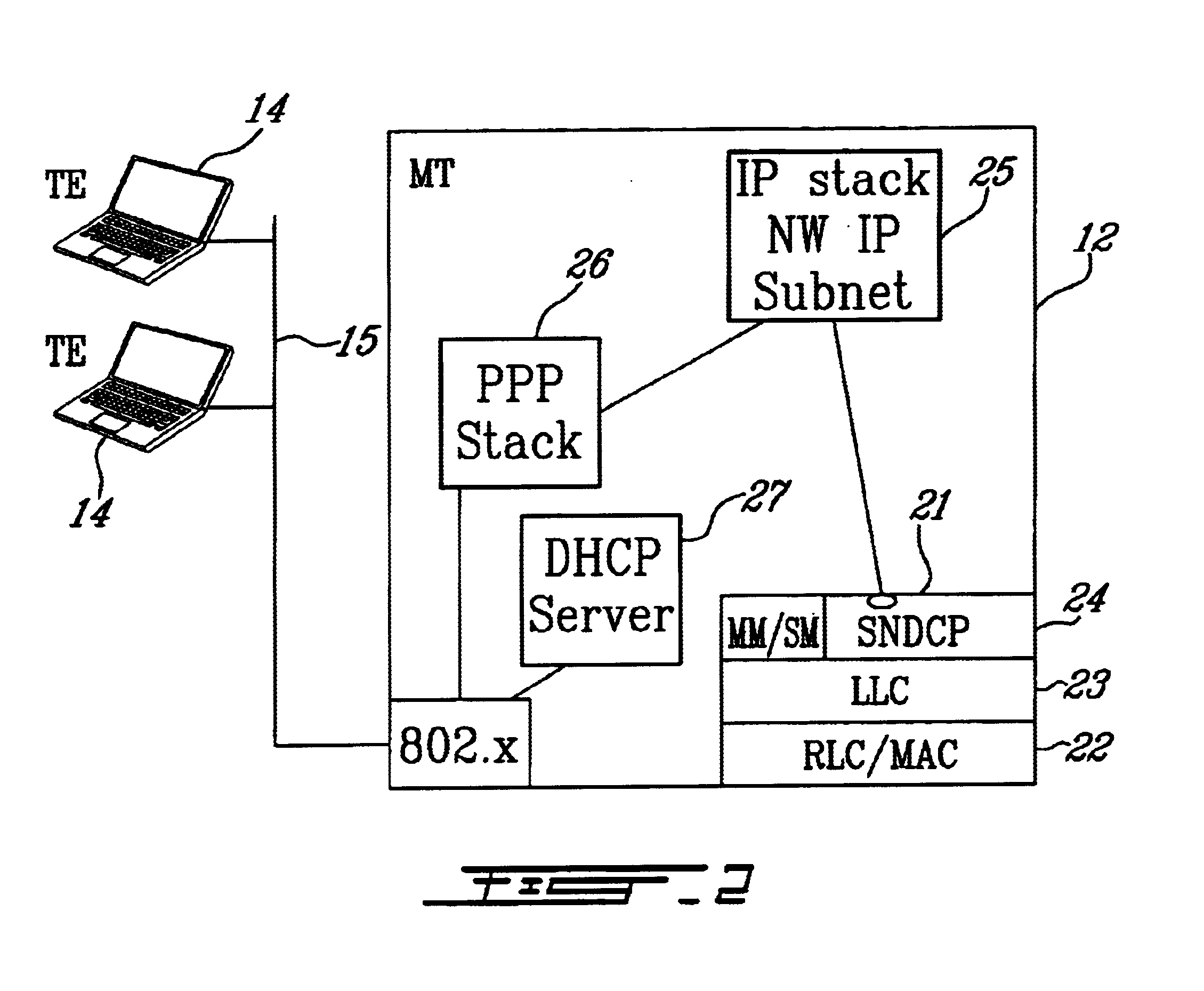
FIG. 2 is a simplified functional block diagram of a first embodiment of a mobile terminal 12 in which a DHCP server is utilized to interface a plurality of TEs with a PDN. The MT includes a radio side protocol stack 21 comprising a Radio Link Control / Medium Access Control (RLC / MAC) protocol layer 22, a Logical Link Control (LLC) layer 23, and a Sub-Network Dependence Convergence Protocol (SNDCP) layer 24. Mobility Management / Service Management (MM / SM) is also performed at this layer. On top of the SNDCP layer is an IP stack 25 to which a network address comprising a plurality of individual IP addresses is passed from the PDN 18. The IP stack is linked to a PPP stack 26 which establishes a link between the TEs 14 and the MT 12. A DHCP server 27 is implemented to assign the multiple IP addresses included in the network address to the TE hosts and devices connected to the LAN 15. The PPP stack then provides the dynamic IP addresses to the TEs using 802.x.
FIG. 3 is a flow chart illustr...
embodiment 2
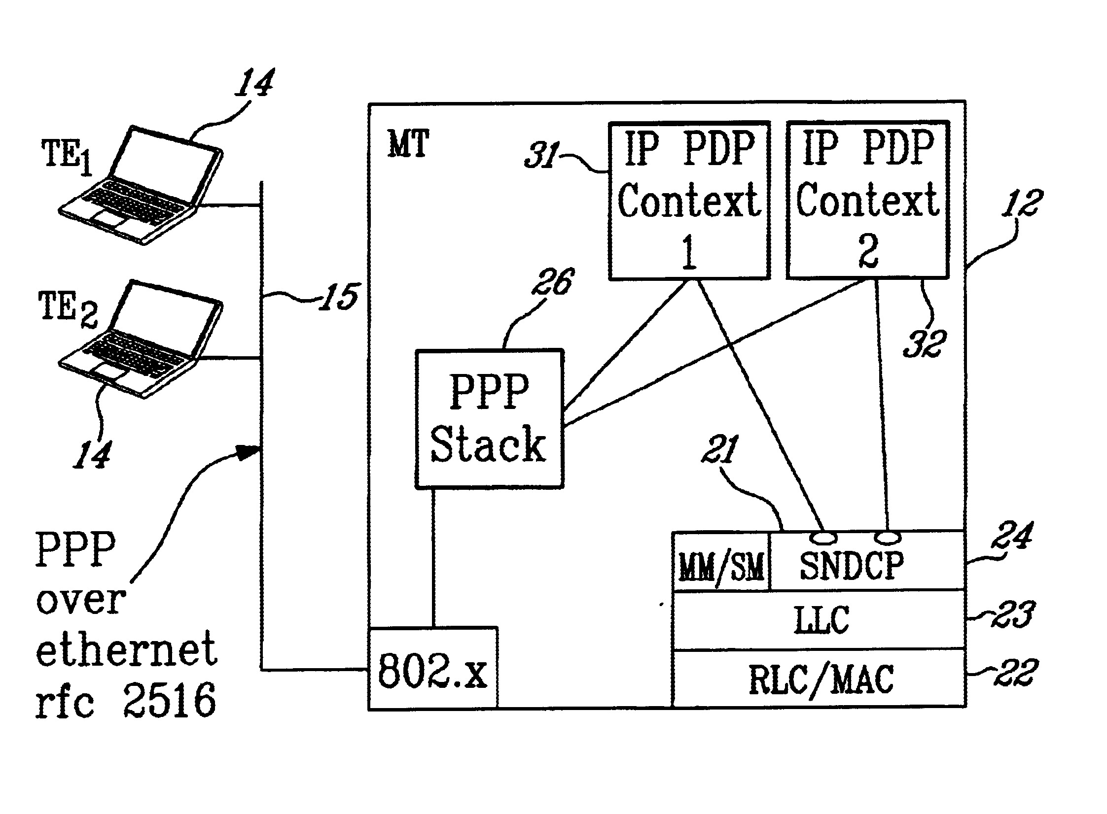
FIG. 4 is a simplified functional block diagram of a second embodiment of a mobile terminal 12 in which PPP over Ethernet (PPPoE) is utilized to interface a plurality of TEs with a PDN. As described above, the MT includes the radio side protocol stack 21 comprising the RLC / MAC protocol layer 22, the LLC layer 23, and the SNDCP layer 24. On top of the SNDCP layer, a plurality of PDP Contexts 45 and 46 are established: one for each TE 14 connected to the LAN 15. The PDP Contexts connect to the PPP stack 26 which establishes a link between the TE 14 and the MT 12 using 802.x.
FIG. 5 is a flow chart illustrating the steps of the second embodiment of the method of the present invention. Once again, at step 51, the TEs and the MT are connected on a network such as a wired or wireless LAN. At 52, each TE workstation on the LAN launches a PPP over Ethernet (PPPoE) session with the MT 12 as per rfc 2516. The session ID parameter defined in rfc 2516 is used as an identifier for each PPP host T...
PUM
 Abstract
Description
Claims
Application Information
 - R&D
- Intellectual Property
- Life Sciences
- Materials
- Tech Scout
- Unparalleled Data Quality
- Higher Quality Content
- 60% Fewer Hallucinations
Browse by: Latest US Patents, China's latest patents, Technical Efficacy Thesaurus, Application Domain, Technology Topic, Popular Technical Reports.
© 2025 PatSnap. All rights reserved.Legal|Privacy policy|Modern Slavery Act Transparency Statement|Sitemap|About US| Contact US: help@patsnap.com


