
Coated hard alloy

a hard alloy and coating technology, applied in the field of coating hard alloys, can solve the problems of accelerating wear, coarsening of crystal grains of the oxide layer constituting the coating, and uneven surface of the tool

Inactive Publication Date: 2004-06-29
SUMITOMO ELECTRIC IND LTD
View PDF14 Cites 40 Cited by
  • Summary
  • Abstract
  • Description
  • Claims
  • Application Information

AI Technical Summary

Benefits of technology

The present invention offers a coated hard metal cutting tool with improved resistance to wear, chipping, welding, and flaking. The coating is composed of multiple layers, including an inner layer, intermediate layer, and outer layer. The face roughness of the outer layer is reduced, resulting in improved resistance to wear and chipping. The coating can maintain superior properties for a long time and is suitable for high-speed cutting and dry cutting.

Problems solved by technology

However, when the thickness of the oxide layer (especially the aluminum oxide layer) is increased to 1.5 .mu.m or more, the crystal grains of the oxide layer constituting the coating become coarsened, developing an unevenness on the surface of the tool in response to the grain size.
This unevenness allows the chips of the work material to apply local stresses to the surface of the tool, accelerating the wear and decreasing the toughness.
The welded portion in turn becomes a starting point of stress application, causing flaking of the layer or chipping.
As a result, the lifetime of the cutting tool is shortened.
This method undoubtedly decreases the grain size of the aluminum oxide.
On the other hand, this method increases the number of interfaces between an aluminum oxide layer and an layer made of another substance, causing flaking to occur easily at the interface.
The flaking develops rapid damage, decreasing the lifetime of the tool.
Although this method can increase the lifetime of the cutting edge, the aforementioned face unevenness of the oxide layer remains as a concavity on the cutting face that cannot be processed by polishing.
This remaining face unevenness accelerates crater wear and other types of wear, decreasing the lifetime of the tool.
This method, however, produces on the surface of the tool an unevenness corresponding to the size of the crystal grains of the aluminum oxide in the outer layer, causing a decrease in the lifetime of the tool.
However, in Tokukouhei 8-158052, the face roughness of an intermediate layer is transferred to an outer layer without improvement.
As a result, the hard metal as the base material deforms plastically, raising the cutting resistance and thereby leading to fracture.
However, the foregoing oxide and titanium carbonitride have low strength for mutual bonding.
Consequently, if an ordinary coating method is used, it will flake off during use.
The titanium carbonitride layer having such a specific property cannot be obtained by ordinary methods.
(a) First, the surface of a hard metal is coated with an inner layer.
Second, the inner layer is coated with an intermediate layer composed of an oxide layer that is excellent in chemical stability and resistance to heat and that is coarse in grain size.
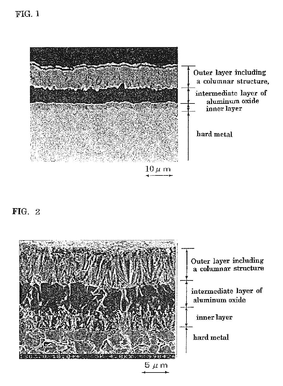
Third, the intermediate layer is coated with an outer layer including a layer of titanium carbonitride having a columnar structure (a crystal structure having a columnar construction) in such a manner that the face unevenness of the intermediate layer can be absorbed by the outer layer. FIG. 2 shows the columnar structure in the outer layer. This photograph shows a fractured section of a coated hard metal.
(b) Face unevenness is intentionally formed on the surface of the oxide layer in the intermediate layer so that the bonding strength between the aluminum oxide in the intermediate layer and the outer layer is increased. The conventional method was unable to provide high bonding strength between the two layers.
(c) A reduction in the face unevenness of the outer layer can improve the resistance to wear, to chipping, and to welding of the entire layer, maintaining the excellent properties for a long period of time.
If more than 20 .mu.m, the strength tends to decrease, shortening the lifetime of the tool.
In FIG. 3, diffraction peaks of aluminum oxide are hard to recognize.

Method used


Image

  • Coated hard alloy
  • Coated hard alloy
  • Coated hard alloy

Examples


embodiment 2

A cemented-carbide tool (type: WNMG120408), composed of 85% WC, 5% TiCN, and 10% Co by weight, having a hard-phase-reduced layer at the surface region was prepared as a hard-metal base material. The base material was placed in a CVD apparatus. The apparatus was evacuated and heated to a temperature of 1,050.degree. C. A mixed gas of 2.5% ZrCl.sub.4, 25% nitrogen, and hydrogen as the remainder by volume was introduced into the apparatus to form a ZrN layer, 0.5 .mu.m in thickness, on the base material. Next, a mixed gas of 1% AlCl.sub.4, 0.5% ZrCl.sub.4, 0.2% H.sub.2 S, 4% CO, and hydrogen as the remainder by volume was introduced into the CVD apparatus heated at 1,000.degree. C. to form an intermediate layer, made of a solid solution of aluminum oxide and zirconium oxide, having a thickness of 10 .mu.m.

Direct formation of a titanium carbonitride layer on the intermediate layer tends to facilitate flaking. To avoid this tendency, a zirconium carbide layer, 1.5 .mu.m in thickness, was...

embodiment 3

As a material for a hard-metal base material, a powder for a cemented carbide composed of 84% WC, 4% TiC, 2% ZrC, 2% NbC, and 8% Co by weight was pressed. The pressed body was sintered in a vacuum at a temperature of 1,400.degree. C. for one hour. The sintered body was subjected to surface polishing and cutting-edge treatment. Thus, a cemented-carbide base material consisting mainly of tungsten carbide and having a shape of ISO CNMG120408 was prepared. On the surface of this base material, a hard coating was formed by using the CVD method.

Table I shows typical manufacturing conditions for the coatings used in the present invention. In the examples below, the layers were formed by controlling only the coating time under the conditions shown in Table I unless otherwise specifically expressed.

Table II shows the constitutions and the thicknesses of the inner layers of the various samples. Table III shows the constitutions, the thicknesses, and the .alpha.-type aluminum oxide' s oriented...


PUM

PropertyMeasurementUnit
temperatureaaaaaaaaaa
thicknessaaaaaaaaaa
lengthaaaaaaaaaa

Abstract

A coated hard metal which has high resistance against wear, chipping, welding, and flaking is offered. The coated hard metal is provided with an inner layer, intermediate layer, and outer layer on the surface of the hard metal. The inner layer includes a layer comprising at least one member selected from the group consisting of (a) the carbides, nitrides, borides, and oxides of the elements belonging to the IVa, Va, and VIa groups in the periodic table and (b) the solid solutions of these. The intermediate layer includes a layer comprising at least one member selected from the group consisting of aluminum oxide, zirconium oxide, and their solid solution. The outer layer includes a layer of titanium carbonitride having a columnar structure. In a cross section showing the structure of the coated hard metal, the relation between "Amax," which signifies the maximum roughness at the outer face of the intermediate layer, and "Bmax," which signifies the maximum roughness at the outer face of the layer carbonitride having a columnar structure in the outer layer, satisfies equation 1.where 0.5 mum<Amax<4.5 mum, and 0.5 mum<=Bmax<=4.5 MUM.

Description

The present invention relates to a coated hard metal, particularly one that is most suitable for cutting tools, that has high resistance against wear, chipping, welding, and flaking, and that can maintain the superior properties over an extended period of time.DESCRIPTION OF THE BACKGROUND ARTTools made of coated hard metal have become commercially practical and have come into wide use. The tool has a hard metal surface which is coated to improve the cutting property. The coating is composed of one or more layers of titanium carbide, titanium nitride, titanium carbonitride, or aluminum oxide, for example. The coating is deposited by chemical vapor deposition or physical vapor deposition.Being non-oxide layers, such titanium-based coatings are useful in improving resistance to wear and to chipping. Oxide layers such as an aluminum oxide layer and a zirconium oxide layer are considered to be suitable for use in a temperature range exceeding 700.degree. C. (high-speed cutting range) at...

Claims


Application Information

Patent Timeline
Patent Type & Authority Patents(United States)
IPC IPC(8): C23C30/00C23C16/36
CPCC23C16/36C23C30/005Y10T428/265Y10T428/24628Y10T428/24364Y10T428/24975
Inventor OKADA, YOSHIOMORIGUCHI, HIDEKIIKEGAYA, AKIHIKO
Owner SUMITOMO ELECTRIC IND LTD
Learn More