
Ligand binding assay and kit with a separation zone for disturbing analytes

a technology of separation zone and assay, which is applied in the field of ligand binding assay and kit with separation zone for disturbing analytes, can solve the problems of complicated signal formation, high equipment cost, and special education of personnel, and achieve the effect of simple and rapid method and facilitate the determination of analytes

Inactive Publication Date: 2004-05-18
MAIIA
View PDF23 Cites 55 Cited by
  • Summary
  • Abstract
  • Description
  • Claims
  • Application Information

AI Technical Summary

Benefits of technology

"The invention is a method for determining an analyte in the presence of disturbing components, especially in samples containing soluble or suspended components. The method uses a flow matrix with separation zones that allow for the retardation of components that may interfere with the detection of the analyte. The method can be performed in field environments and at advanced laboratories. It also allows for the rapid and simple evaluation of libraries of compounds. The invention provides a simple and rapid method for determining analytes in samples containing disturbing components."

Problems solved by technology

Other indirectly disturbing components, for example heterophilic antibodies, may be present in the original sample and interfere with the formation of the signal complex in DZ.
Problems with disturbing components in samples have often meant that for analytes that are present in low concentrations, the separation of disturbing components and the detection have been performed in different systems.
The ion-exchange chromatography separation is controlled from an advanced and costly equipment, which requires specially educated personnel.
Also the traditional immunological tests are expensive and require well-educated personnel.
Transport of whole cells into DZ may interfere with the signal from the detection complex.

Method used


Image

  • Ligand binding assay and kit with a separation zone for disturbing analytes
  • Ligand binding assay and kit with a separation zone for disturbing analytes
  • Ligand binding assay and kit with a separation zone for disturbing analytes

Examples


example 1

Test Strip for Measurement of the Proportion of Free IgE, IgE Bound to IgG and Antibodies to IgE

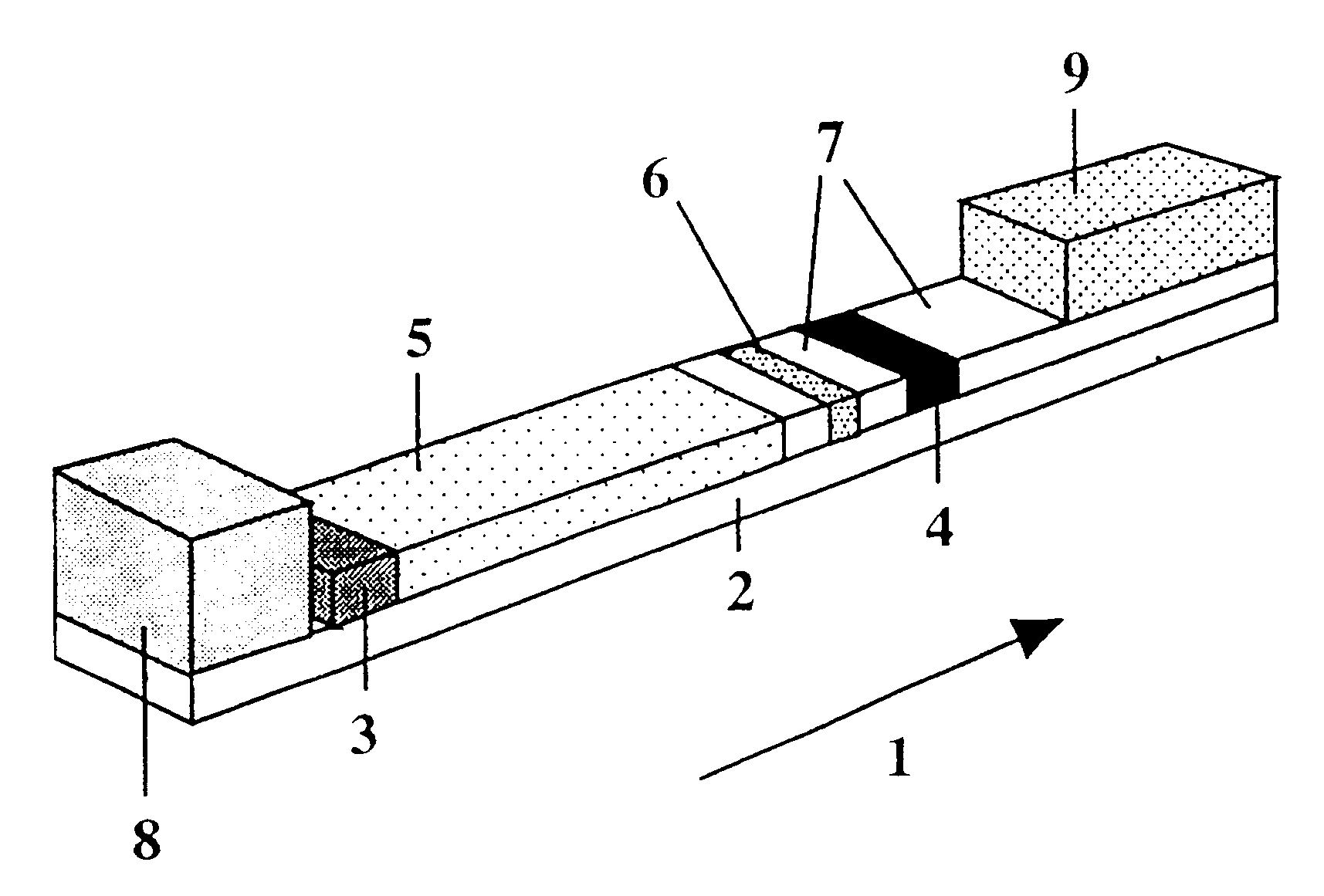
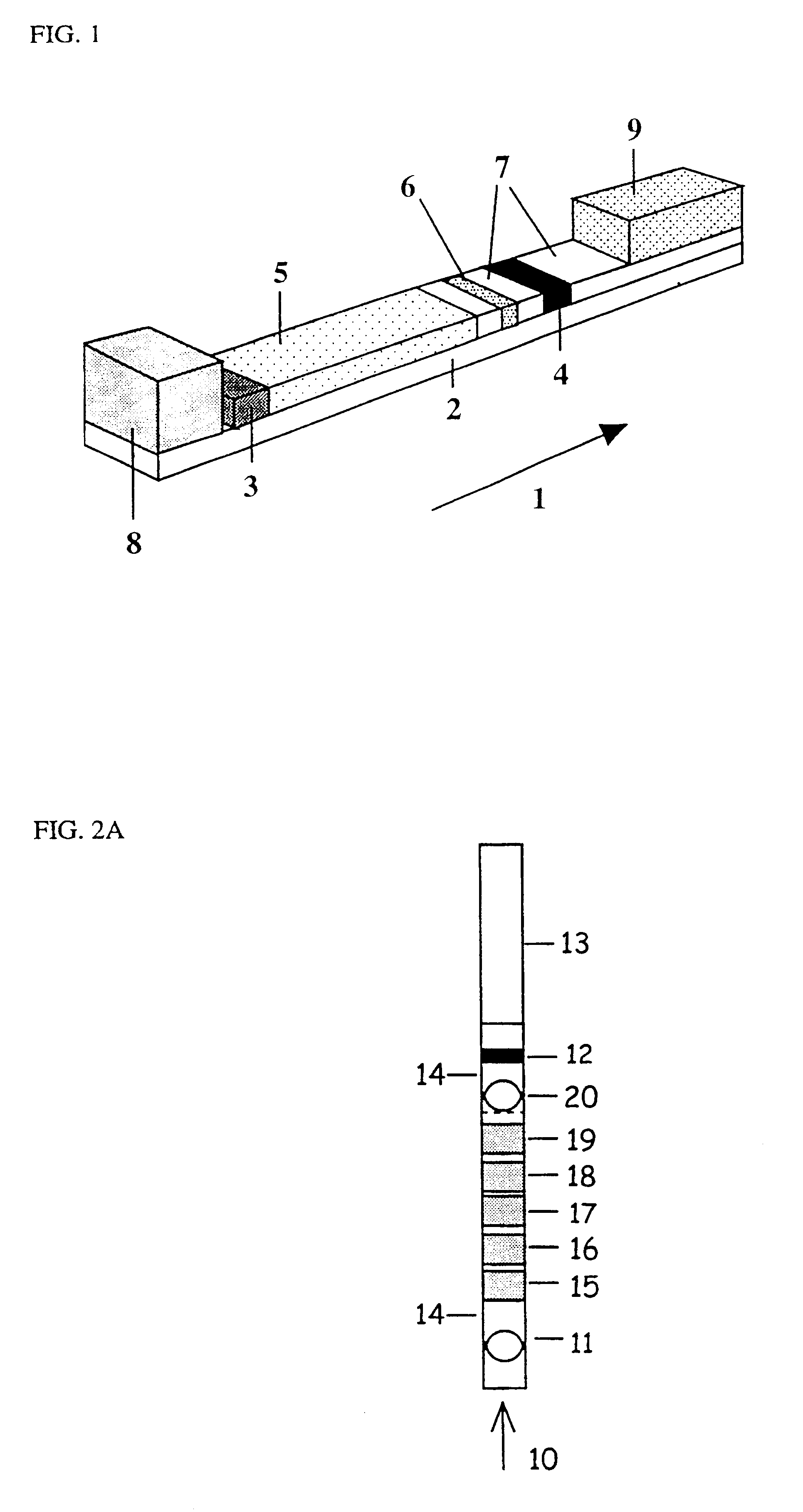
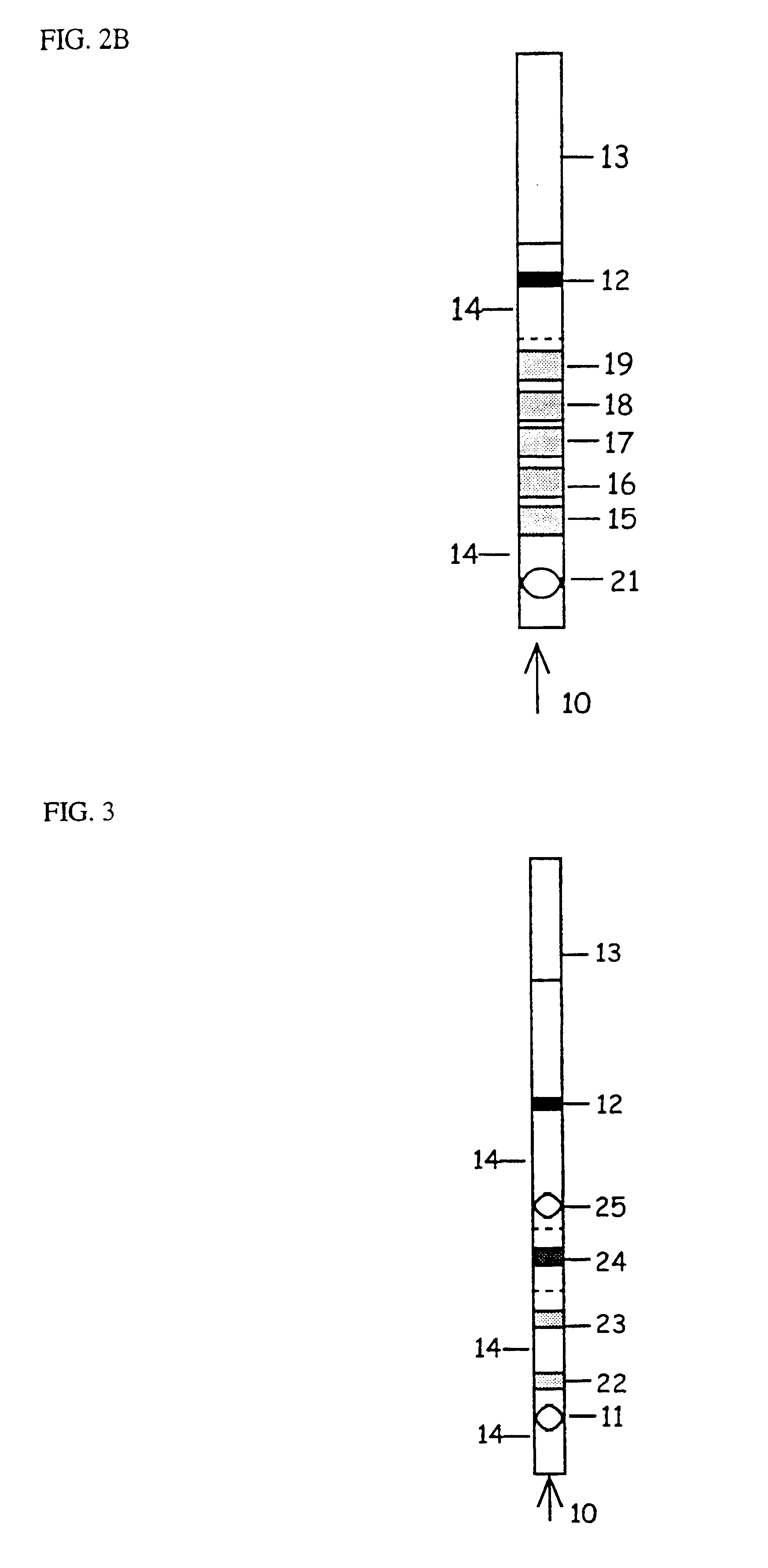
In FIGS. 2A, 2B and 3 the direction of the transport flow is indicated by an arrow (10). In each variant there may at the beginning of the transport flow be a zone ASZ (11) for sample, downstream thereof a zone DZ (12), at the end of the transport flow a sucking part (13), and between each type of zone, parts which only serve as transport zones (14).

FIG. 2A

The variant according to this figure has five separation zones (SZ) in which the ligand may be the same or different or be present in different amounts (15-19) and an AR*Z (20) for reagents.

FIG. 2B

This is the same sequence of zones as in FIG. 2A except that ASZ (11) and AR*Z (20) coincide (21). This zone sequence may also be used for the cases where the analyte per se is detectable when it is part of a signal complex in DZ. An AR*Z is then not necessary.

FIG. 3

The sequence of zones according to this figure exhibits two types of separatio...

example 2

Determination Method for CD-Transferrin in Patient Samples

Separation Membrane Having Anion-exchanging Properties

A sheet of nitrocellulose membrane (5 .mu.m, nitrocellulose on polyester, Whatman International Ltd, England) was placed in a solution of 0.1% polyethylene imine (PEI, Sigma, St Louis, Mo., U.S.A.) in ultrapure water (Milli Q, Millipore Corp., Bedford, Mass., U.S.A.). The solution was shaken for 3 hours and then placed in 0.1% in Tween 20 for 30 minutes, air-dried and then stored in a plastic bag at +4.degree. C. The modification degree of the membrane was checked with bromophenol blue (pK=4.1).

The function of modified membranes to interact with charged proteins was confirmed by transporting .sup.125 I-labelled proteins (bovine serum albumin, tetrasialo- and asialo-transferrin which had been labelled by the Chloramine T method) in a lateral liquid flow in strips of the sheet. The protein having the highest pI had the strongest tendency to migrate with the liquid flow. If t...

example 3

Test Strip with Sambucus Nigra Lectin in the Separation Zone

Separation Membrane

A sheet (4 cm.times.12 cm) of cellulose (cellulose filter 54, Whatman International Ltd, England) was activated with cyano-diethyl-aminopyridine (CDAP) (Kohn and Wilchek, Appl. Biochem. Biotechnol. 9 (1984) 285-304). The activated sheet was placed in a solution of 0.1 mg / ml of Sambucus Nigra lectin (binds sialic acid which is in the terminal position of a carbon chain; Vector Laboratories Inc., Burlingame, Calif., U.S.A.) in 0.1 M NaHCO.sub.3, pH 8.4. The solution was shaken for 2 hours, and the sheet was then placed in a) 0.1 M NaHCO.sub.3, b) 0.5 M NaCl, c) distilled water, d) 0.1 M acetate buffer, pH 4.5, e) 0.1 M NaHCO.sub.3, pH 8.4, f) 0.5 M NaCl, g) distilled water, h) 0.1 M acetate buffer, pH 4.5, i) 5 mM BIS-TRIS, pH 6.4, containing 0.1% Tween 20. Between the different baths, excess liquid was sucked off by means of kitchen roll paper. After the wash procedure, the sheet was air-dried and stored i...


PUM

PropertyMeasurementUnit
sizeaaaaaaaaaa
sizeaaaaaaaaaa
sizeaaaaaaaaaa

Abstract

The invention relates to a method for determining an analyte by means of binding reactions, which method comprises: i) applying the sample to an application zone for sample (ASZ) on a flow matrix in which transport of components present in the sample can take place (transport flow), the flow matrix further exhibiting: a) optionally an application zone (AR*Z) for a binding reactant (Reactant*=R*) which is analytically detectable; b) a detection zone (DZ), which is located downstream of ASZ and exhibits an additional binding reactant (Capturer) firmly anchored to the matrix, and in which a complex (signal complex) containing the Capturer and the analyte and / or Reactant* is formed during the reaction, and ii) detecting the signal complex in the detection zone, the measured signal being used for determining the analyte. According to the invention, the flow matrix comprises at least one separation zone (SZ) between ASZ and DZ, which zone exhibits a structure (ligand) having binding capability for a component that is transported in the matrix and which would affect the measurable signal if the component is transported into DZ. The invention also relates to a test kit comprising the flow matrix.

Description

The invention relates to a method for determining an analyte in a sample and to a kit for use in the method.Starting from the prior art, the method of the invention comprises the steps:i. The sample is applied in a sample application zone (ASZ) on a flow matrix in which transport of components present in the sample may take place (transport flow). The flow matrix further comprises:a) optionally an application zone (AR*Z) for a binding reactant (Reactant*=R*) which is analytically detectable,b) a detection zone (DZ) which is located downstream of ASZ and exhibits another binding reactant (Capturer) firmly anchored to the matrix and in which a complex (signal complex) containing the Capturer and the analyte and / or the Reactant* is formed in the method.ii. The flow is allowed to effect the transport of sample components.iii. The signal complex is detected in the detection zone and the measured signal is used for the determination of the analyte.The invention is primarily directed to th...

Claims


Application Information

Patent Timeline
Patent Type & Authority Patents(United States)
IPC IPC(8): G01N33/558G01N33/543
CPCG01N33/54386G01N33/558Y10S436/825Y10S435/97Y10S436/81G01N33/54388
Inventor CARLSSON, JANLONNBERG, MARIA
Owner MAIIA
Learn More