
Torque measuring device for a device measuring the flow of material

a technology of torque measurement and material flow, which is applied in the direction of mass flow measurement devices, measurement devices, instruments, etc., can solve the problems of increasing the effort and expense of the measuring device, and falsifying the measuremen

Inactive Publication Date: 2004-03-16
SCHENCK PROCESS GMBH
View PDF12 Cites 15 Cited by
  • Summary
  • Abstract
  • Description
  • Claims
  • Application Information

AI Technical Summary

Benefits of technology

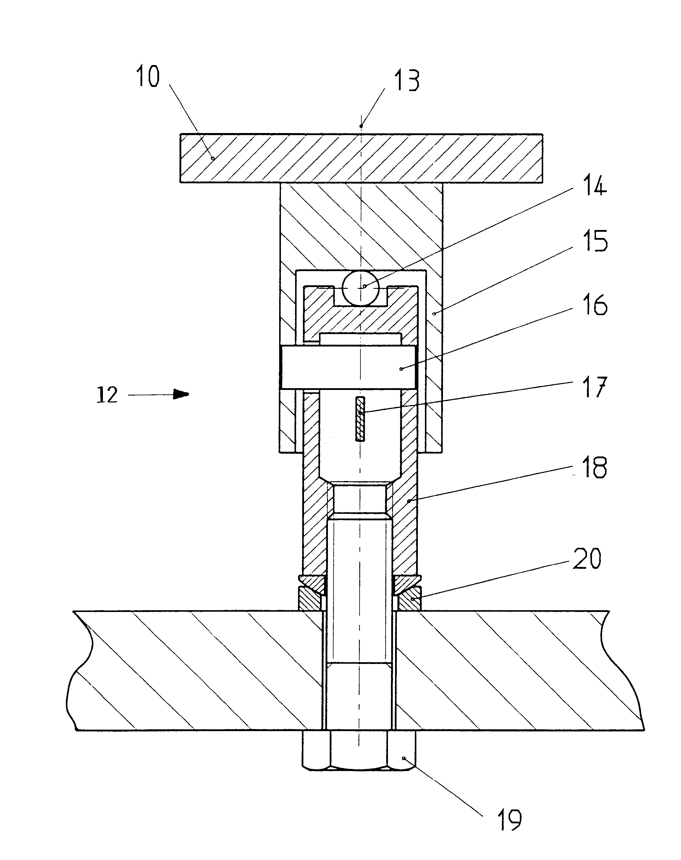
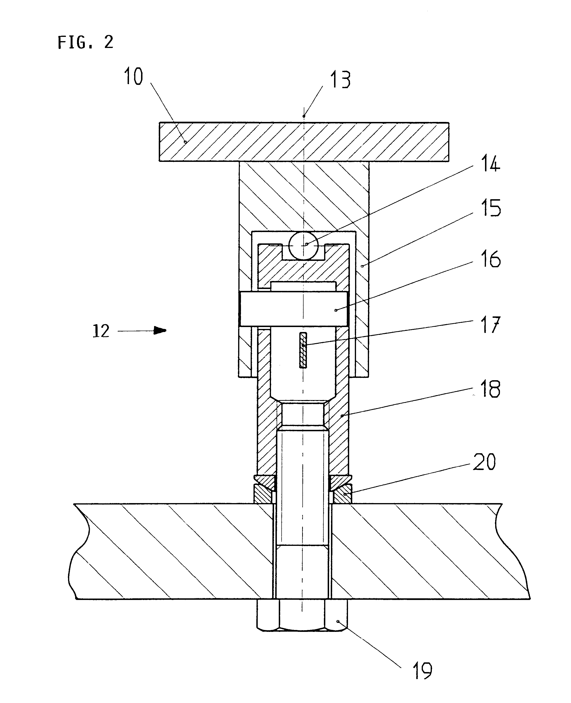
The invention has the advantage that due to the crosswise arranged leaf spring elements, the measuring device always remains fixed on a predetermined rotational axis. Thus, the lever arm length for bearing on a stationary force measuring device cannot vary so that a good zero point stability and measuring value constant is achievable. By these features simultaneously a good insensitivity to temperatures is achieved because the heat expansions can become effective on the lever arm length only in a negligible manner.
According to a special type of embodiment of the invention with an axial ball or toe bearing, it is an advantage that thereby the weight of the drive train is transferrable substantially with low friction onto a stationary housing section, whereby friction caused measuring errors have become substantially avoidable. The drive train includes the impeller, the drive shaft, and the motor. Due to the fact that in such an embodiment the rotation bearing does not have to take up any axial forces, hardly any force shunting effect takes place so that with such a measuring device even small conveying volumes are measurable in an advantageous way and manner. In such an axial support it is also advantageous that the support can be protected in a simple manner against contaminations so that precision is assured over long periods of time.
In a further advantageous embodiment of the invention a friction free horizontal mounting of the drive shaft is achieved with the aid of a fluid bearing in the lead through area so that here friction related measuring errors are also avoided. Simultaneously such a fluid or air bearing assures an excellent sealing to the bulk material space so that the measuring device is advantageously also operable with excess pressure without any apprehension that a contamination and friction increase of the bearing might occur.

Problems solved by technology

Even if one ascertains this bearing friction by a measurement made during an empty run and then takes the measurement into account, different bearing frictions occur under load operating conditions so that with a motor supported at one side, due to a non-uniform lubrication on the bearing walls, frictions occur that cannot be determined and which falsify the measuring result.
However, for this purpose at least two force measuring elements are required which increase the apparatus effort and expense of the measuring device.

Method used


Image

  • Torque measuring device for a device measuring the flow of material
  • Torque measuring device for a device measuring the flow of material
  • Torque measuring device for a device measuring the flow of material

Examples


Embodiment Construction

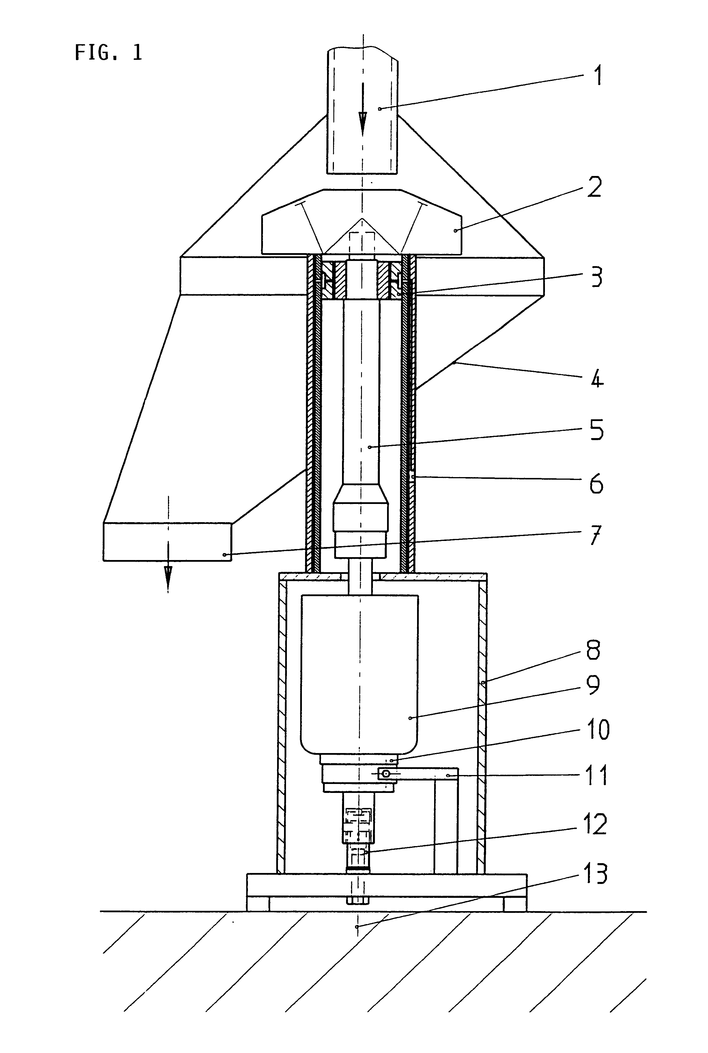
FIG. 1 of the drawings shows schematically in a sectional view a device for measuring a mass flow in which the impeller 2 is arranged above the drive motor 9 on a lengthened drive shaft 5 and wherein the drive moment is transmitted through a pivot bearing element 12 onto a force sensor 11 as a torque moment measuring device.

The mass flow which is mostly a bulk material flow is guided through a tubular bulk material supply 1 to the center of an impeller 2. The impeller 2 is driven by the drive motor 9 with a constant speed, whereby the bulk material flow is horizontally deflected and flows downwardly through the surrounding bulk material housing 4 and through a bulk material outlet 7. The impeller 2 is mounted on an elongated vertical drive shaft 5 which is mounted by an air bearing 3 horizontally relative to the bulk material housing 4. By means of this air bearing 3 simultaneously a sealing is achieved relative to the bulk material housing 4 so that a contamination of the bearing 3...


PUM


Abstract

The invention relates to a device for measuring the flow of material, especially of a flow of bulk material, according to the Coriolis principle of measurement. The device has an impeller (2) which is driven by a motor (9) with a constant r.p.m. The flow of material is fed to the impeller (2) and is radially deflected. The driving torque is measured by a torque measuring sensor. The driving torque is transmitted to a force sensor (22) by a pivot bearing (12) for determining the torque. The force-sensing element (22) has at least two horizontal leaf springs (16, 17) which cross each other and which are arranged in such a way that the crossing point of the leaf springs (16, 17) coincides with a rotational axis (13). A thrust bearing (14) is integrated into the pivot bearing (12). The weight of the drive train is transmitted to a stationary housing (8) by the thrust bearing (14) with the help of a ball bearing or toe bearing. A frictionless air bearing (3) is provided for horizontally supporting the drive shaft (5) in order to improve the measuring accuracy.

Description

The invention relates to a device for measuring a mass flow, particularly of a bulk material flow whereby the Coriolis measuring principle is employed.BACKGROUND INFORMATIONFor a precise ascertaining of the weight of material flows the effective inertia force (Coriolis force) is utilized for the mass determination. The Coriolis force occurs at the coupling of a moved mass particle with a rotating reference body. For this purpose the material flow is supplied to a disk provided with radial guide vanes, whereby the bulk material is centrifuged substantially perpendicularly to the rotational axis of the disk. The torque moment of the disk rotating with a constant r.p.m. varies in accordance with the Coriolis force, whereby the torque moment change is proportional.Such a measuring device for the continuous ascertaining of the weight of material flows is known from German Patent Publication DE-OS 3,346,145. In that measuring device an impeller rotating with a constant r.p.m. is driven by...

Claims


Application Information

Patent Timeline
IPC IPC(8): G01F1/80G01F1/76
CPCG01F1/80G01F1/8454
Inventor TOERNER, LUDGER
Owner SCHENCK PROCESS GMBH
Learn More