
Information recording apparatus

a recording apparatus and information technology, applied in the field of information recording apparatuses, can solve the problems of jitter inability to ensure the reliability of reproduced information, and decrease in the amplitude of the reproduced signal

Inactive Publication Date: 2004-01-13
HITACHI CONSUMER ELECTRONICS CORP
View PDF8 Cites 26 Cited by
  • Summary
  • Abstract
  • Description
  • Claims
  • Application Information

AI Technical Summary

Benefits of technology

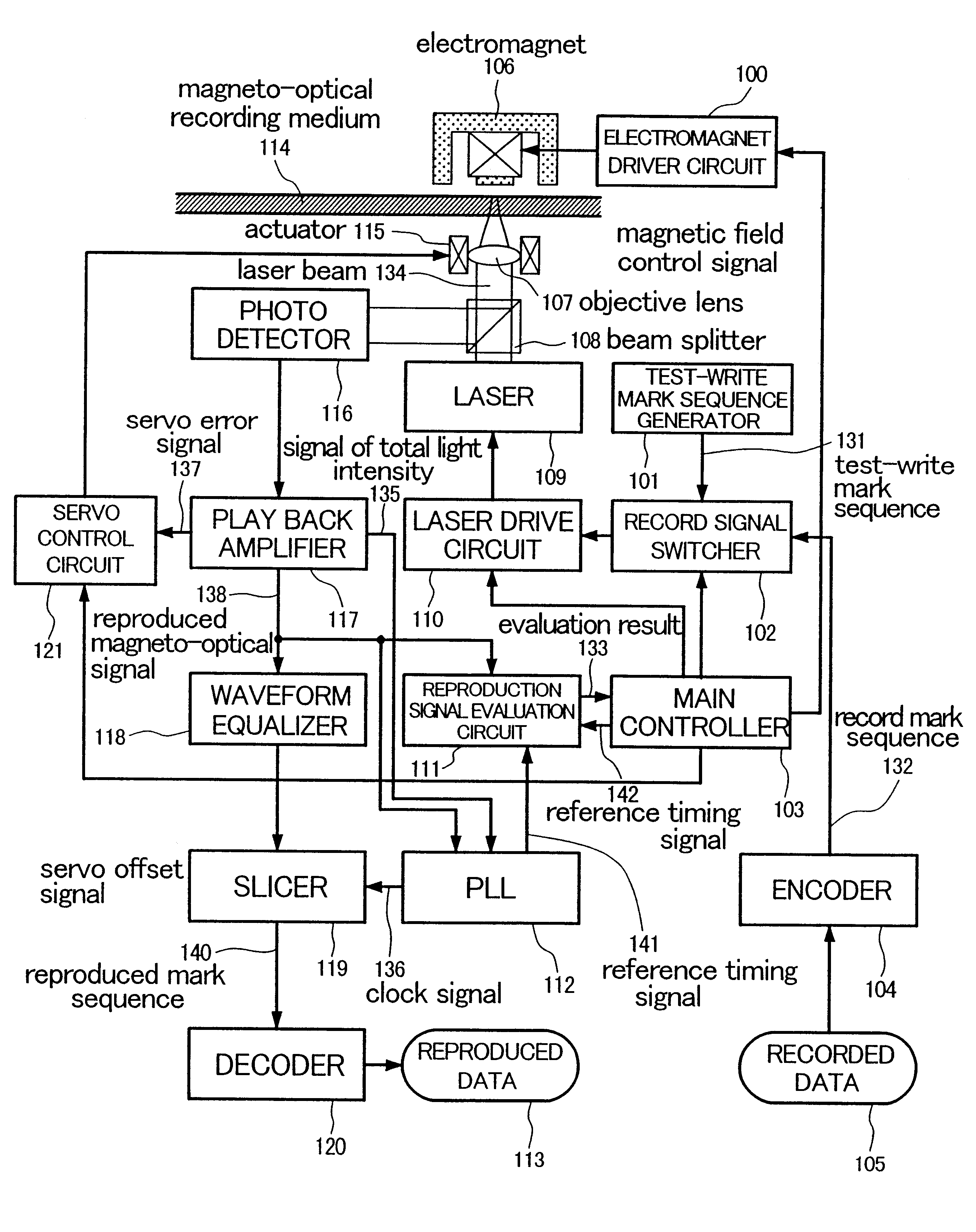
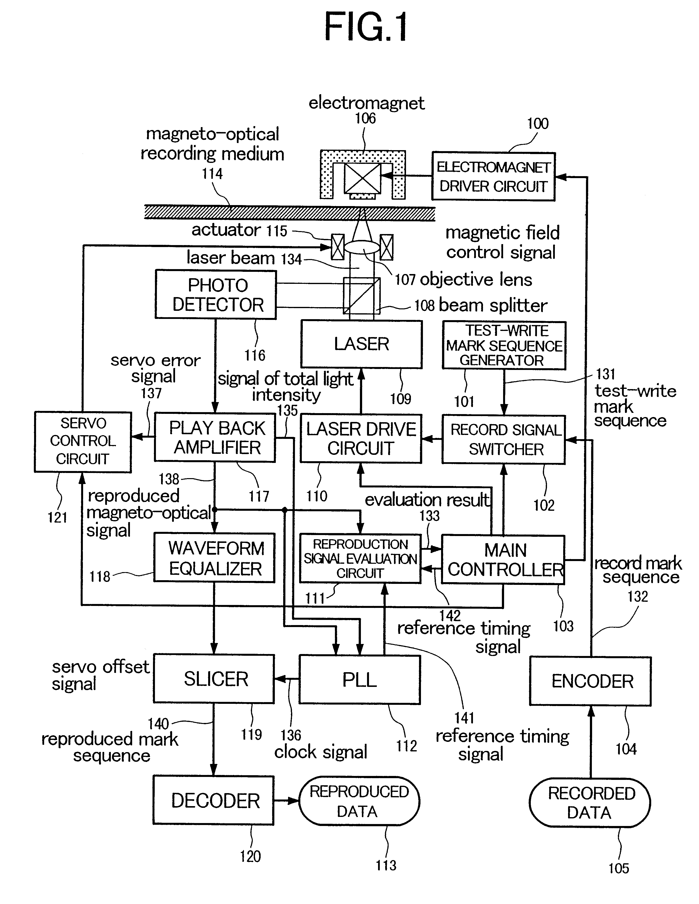
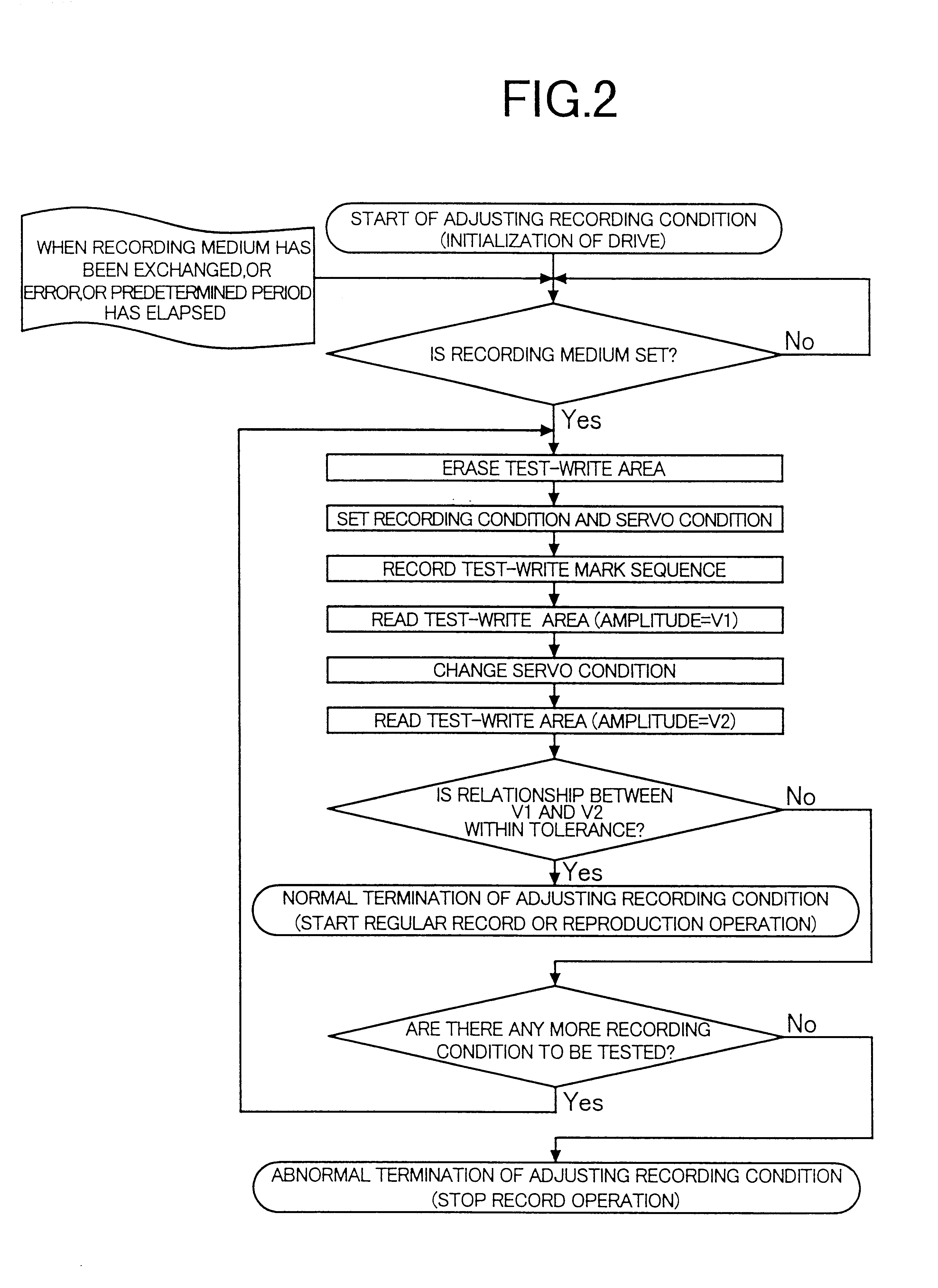
With the aforementioned configuration, the mark width can be detected directly to optimize the recording condition. By the recording condition optimizing operation, variation of the mark shape caused by variation of recording sensitivity of the recording medium due to variation of thickness of the recording layer of the recording medium or variation of the environmental temperature can be reduced as extremely as possible. At the same time, variation in the operating characteristic of the apparatus for performing recording can be reduced. Hence, a very small mark can be formed extremely accurately, so that improvement of recording surface density can be achieved.

Problems solved by technology

That is, if the mark length along a scanning direction of optical spot (tracking direction) is too short, jitter of a reproduced signal increases so that reliability of reproduced information cannot be secured.
If the mark length along the tracking direction is contrariwise too long, jitter of the reproduced signal also increases.
If the mark width along a direction perpendicular to the scanning direction (perpendicular to tracks) of optical spot is too narrow, the amplitude of the reproduced signal decreases so that reliability of reproduced information cannot be secured.
If the mark width in the perpendicular direction is contrariwise too wide, crosstalk in reproduction process with respect to adjacent tracks increases so that reliability of reproduced information cannot be secured and, accordingly, there is a risk of cross-erase that adjacent recorded marks may be destroyed when things come to the worst.
It is, however, very difficult to form stably and accurately a small mark having a size not larger than about a half of the optical spot size when the mark is to be reduced in size for the sake of high-density recording.
Reduction of the wavelength of a semiconductor laser diode which is a typical laser light source is, however, attended with technical difficulty.
Hence, there is the existing state of affairs that no technique has satisfied the demand for increase of recording density.
Accordingly, it was difficult to control the mark width accurately, that is, to determine recording power accurately.
Hence, it was impossible to perform recording / reproduction using small marks at narrow track intervals, so that the first related art was disadvantageous in terms of improvement of recording surface density.
Moreover, the conventional test-write method as disclosed in the first related art cannot be used in the second related art because leading and trailing edges of each mark shift by the same distance in the same direction along the tracking direction even in the case where recording is performed while recording power is changed, as described above.
Hence, it was impossible to control the mark width sufficiently, so that it was difficult to reduce the track pitch.
For the aforementioned reason, in the respective related art, it was therefore impossible to form small marks with sufficient accuracy, so that it was impossible to improve recording surface density.

Method used


Image

  • Information recording apparatus
  • Information recording apparatus
  • Information recording apparatus

Examples


Embodiment Construction

Embodiments of the present invention will be described below. Although description will be made on the assumption that the present invention is applied to a magneto-optical disk device using a light intensity modulation method, it does not limit the shape of the recording medium and the recording method as a subject of the present invention. That is, the medium may be shaped like a tape, a card, etc., and the recording method may be a magnetic field modulation method or a laser-strobe magnetic field modulation method other than the light intensity modulation method. Further, the following description does not intend to limit the recording principle, and the gist of the present invention is also effective for an information recording apparatus based on phase-change recording, or the like. That is, the present invention can be generally applied to information recording apparatuses for recording information by energy irradiation of a recording medium to bring a local physical change of...


PUM


Abstract

An information recording apparatus includes an energy generation device for generating recording energy; a position control device for controlling a position of irradiation on the recording medium with an output of the energy generation device; a drive device for driving the energy generation device; a switching device for switching information based on user data and test information to supply the two kinds of information selectively to the drive device; a reading device for reading the marks recorded on the recording medium; an evaluation device for evaluating a reproduced signal obtained by the reading device; and a recording condition control device for controlling a recording condition on the basis of an evaluation result obtained by the evaluation device, wherein, when the marks used for recording the test information are to be reproduced, controlling operation of the position control device is changed to be different from that used for recording the test information.

Description

1. Field of the InventionThe present invention relates to an information recording apparatus for recording information by a local physical change in a recording medium due to energy irradiation, and exclusively relates to an optical disk device.2. Description of the Related ArtCurrently available optical disk-medium and device combinations can be roughly classified into a combination of magneto-optical disks and a magneto-optical disk device of the type of forming a mark by a reversal magnetic domain on a recording layer by heating the recording layer, and a combination of phase-change disks and an optical disk device of the type of forming a mark by an amorphous domain on a recording layer while changing the cooling speed of the recording layer by controlling the quantity of recording energy input at heating. As an example of a method for improving recording density of information to be recorded on such recording media, there is a method in which marks holding information are reduc...

Claims


Application Information

Patent Timeline
IPC IPC(8): G11B11/105G11B11/00G11B7/09G11B7/004G11B7/00G11B7/003G11B7/0045G11B7/0055G11B7/125
CPCG11B7/1267G11B11/1053G11B11/10556G11B11/10595G11B7/094G11B7/00
Inventor SAGA, HIDEKI
Owner HITACHI CONSUMER ELECTRONICS CORP
Learn More