Eureka AIR delivers breakthrough ideas for toughest innovation challenges, trusted by R&D personnel around the world.

Pouch and method of producing film for pouch

a pouch and film technology, applied in the field of pouches, can solve the problems of high cost of pouring parts, difficulty in controlling the direction of content pouring, and difficulty in easiness and safety of pouring,

Inactive Publication Date: 2003-12-23
DAI NIPPON PRINTING CO LTD
View PDF8 Cites 74 Cited by
  • Summary
  • Abstract
  • Description
  • Claims
  • Application Information

AI Technical Summary

Benefits of technology

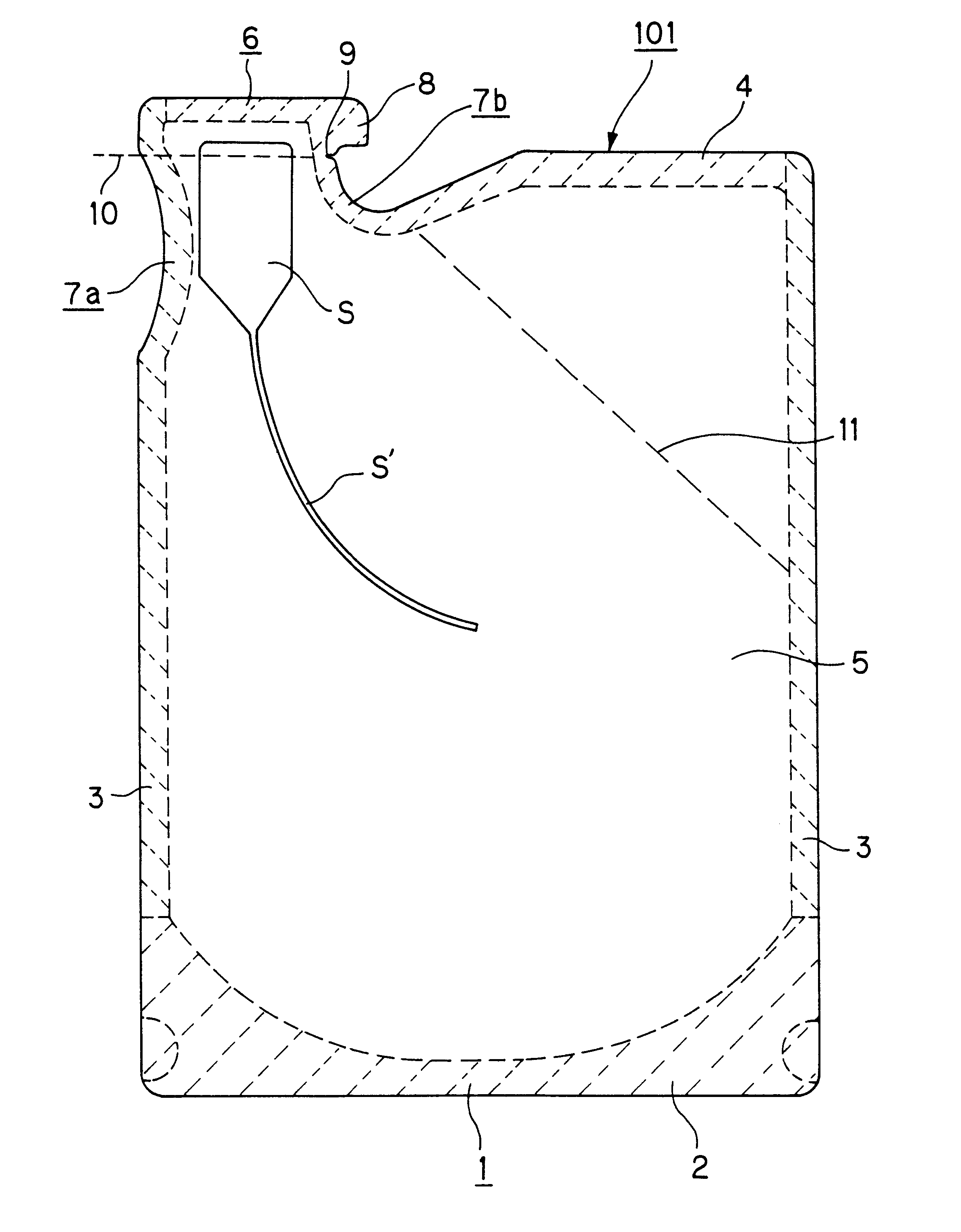
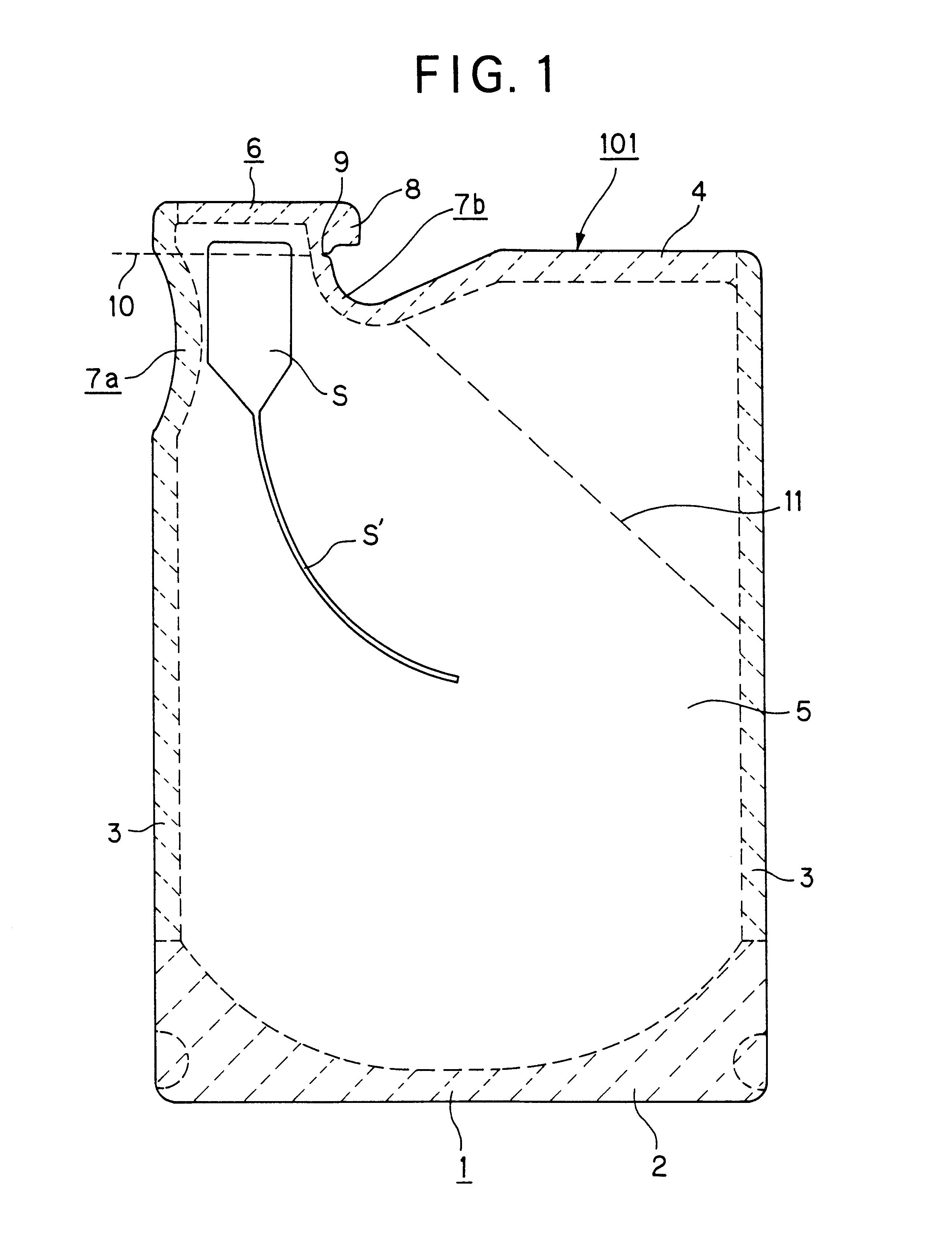
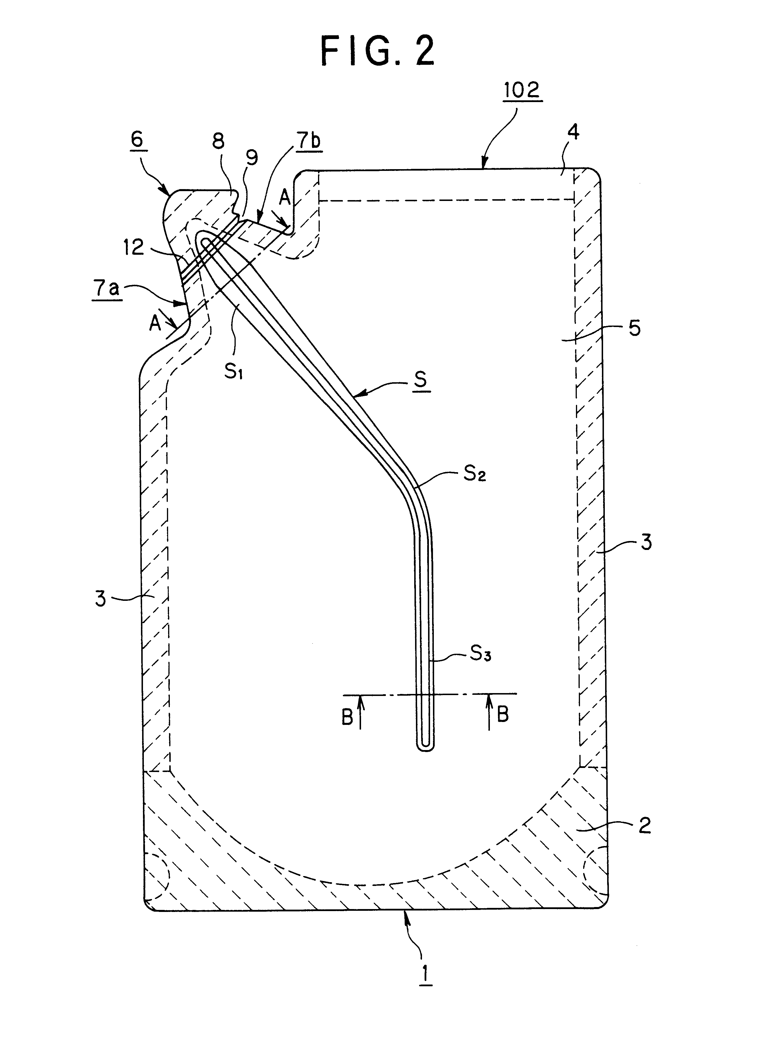
A third object of this invention is to provide an easy open pouch excellent in safety and productivity, in which a half-cut line having an improved shape is formed at a tearing position of the pouch, and it is possible to easily tear the pouch along the half-cut line at the time of an opening operation, and breakage or splitting of the half-cut line is not caused on the ordinary operations in a production process or a distribution stage, and the pouch is applicable to various pouches including a flat pouch such as a three-side sealed type or a four-side sealed type, and it is particularly applicable to a pouch liable to get an actual torn direction off the intended cut line, such as the pouch concerned with the first object because of its bulge portion. The bulge portion will be explained herein after.
When the pouch of the third invention is opened, an opening position of the pouch can be easily and exactly torn along the half-cut line. In addition, the pouch of the third invention is prevented from being ruptured, thus being excellent in safety of storage.

Problems solved by technology

The manner to cut out the corner of the pouch is easy, but it is difficult for this manner to control pouring direction of the content.
In particular, when the content is poured into a container having a small opening such as tapered bottle, an opening of the pouch which is small and flexible is liable to get off the aimed opening of the container during a course of pouring to spill the content out, thereby causing problems in easiness and safety of pouring.
As to the other manner in which a separately formed pouring parts such as a plastic mold product is mounted at one position of the upper portion of the pouch, this manner needs many steps to produce the pouch, and also causes high cost of the pouring parts it self.
In addition, since the pouch provided with the separately formed pouring parts is relatively thick, cost for storing or transporting gets expensive.
Accordingly, this manner causes problems of a large cost and a complicated process.
However, when the pouring portion formed in such a manner is torn and opened, the thus formed opening of the pouring portion is not easily expanded, and flow of pouring is not steady.
In particular, when an amount of the remaining content gets small, the opening of the pouring portion is liable to spontaneously close, and if the pouch is pushed in this condition in order to push out the content, the content may flush and spill out.
Accordingly, Even this manner also causes the problems in easiness and safety of pouring operation.
However, since the notch can not control tearing to be developed in a constant direction, it is difficult to tear the pouch along a cut line indicating desired direction only by the notch.
However, the manner using the uniaxial oriented film causes an expensive cost of a material.
Besides, when the cut line is set inclined with respect to an axis of the pouch, it is difficult to align the oriented direction of the film with the cut line.
As to the other manner forming the half cut, since irradiation of a laser beam is available to carry out this manner, an initial cost of a laser machine is expensive but a running cost is cheap, and it is easy to form a half-cut line of any direction, thereby providing advances in those points.
To the contrary, when the half-cut line is made deep by increasing a power of the laser beam, a tear strength at the seal portion is reduced and tearing is made easy, but a tear strength at the non seal portion as the middle portion is also reduced and gets excessively weak.
Accordingly, such a pouch is liable to be broken from the half-cut line by some impact, thereby causing a problem in safety.
To the contrary, when the cut line is set at a position upper than the vertex of the assumed right triangle, the force of the bent line to choke the pouring portion can not be removed even after cutting out, thereby choking the pouring portion.
With a height lower than 1.0 mm, improvement in an expanding ability of the opening may be insufficient.
With a height larger than 7.0 mm, it is not necessary to make the bulge portion so high, and a working to form the bulge portion becomes difficult, and further the bulge portion becomes bulky to deteriorate a handling of the empty pouch and a fitness to stacking operation in a filling and sealing machine, thus being undesirable.
Accordingly, it has been difficult for the thermal pressing process to carry out a precise molding according to the die, thus causing a problem.
This problem will get more serious when a film to be molded for the pouch is a lamination film having a construction in which a sealant layer is laminated on a substrate film comprising an oriented film, because such a lamination film is not always suitable for a molding process.
Accordingly, when the bulge portion is subjected to a pushing load caused by, for example, an own weight of stacked pouches, the bulge portion is liable to be collapsed.
However, when the bulge portion is formed to the film for the pouch by such a conventional thermal pressing process, the bulge portion of the pressed film is discharged from the die while it stood still heated, and then sink of molding becomes relatively large.
Accordingly, boundaries between the flat faces defining the bulge portion is shaped into round corners to deteriorate the rib effect, thereby making benefit of the bulge portion insufficient.
Besides, when such pouches are. stacked in a corrugated box in order to store the empty pouch, the pouches are kept bent, thereby causing a bent warp, i.e., one kind of curling.
Further, if the pouches occurring the bent warp are stuck to each other by static electricity, the two stuck pouches is liable to be fed together from the feeder into the filling machine, thereby causing troubles.

Method used


Image

  • Pouch and method of producing film for pouch
  • Pouch and method of producing film for pouch
  • Pouch and method of producing film for pouch

Examples


example 1

The molding process according to the second invention which can form the bulge portion was adapted to the formation of the pouch for refill to form the pouch 117 shown in FIG. 21, in which the bulge portion having such a trapezoidal A--A section as shown in FIG. 22A was formed to each of the front and the rear walls 5, 5' so as to be symmetrically arranged, an overall dimension was set to 110 mm of width and 200 mm of length, and a volume capacity was 250 mm.

Each of the lamination films 5, 5' for the pouch was prepared by taking an oriented nylon(ON) film with a thickness of 25 .mu.m as a substrate film, printing on an inside surface of the ON film with a prescribed design, bonding a L-LDPE film with a thickness of 130 .mu.m as a sealant layer to the printed surface by the dry lamination method.

An apparatus to produce the pouch was constructed in such manner that a molding device comprising two sets of the preheating portion and the molding portion was incorporated with a known mach...


PUM

PropertyMeasurementUnit
Angleaaaaaaaaaa
Sizeaaaaaaaaaa
Flexibilityaaaaaaaaaa

Abstract

A pouch of the present invention comprises a front and a rear walls and a narrow pouring portion, and at least one wall portion is partially protruded to an outward direction of the pouch to be provided with a bulge portion having a hollow structure at vicinity of the pouring portion. Alternatively, a cut line of the pouring portion is positioned based on a vertex of a vertical angle of an assumed right triangle which is drawn at the pouring portion by the predetermined regulations. A half-cut line as an opening aid may be provided to a position to be opened of the pouch, the half-cut line being formed so as to have a combination of a deep part and a shallow part and / or a combination of a wide part and a narrow part. The bulge portion may be formed by subjecting a preheated resin film to press molding with the use of a die comprising a cavity and a core, and then cooling the thus press-molded resin film while it is held in the die.

Description

1. Field of the InventionThe present invention relates to a pouch capable of storing a fluid content such as liquid, viscous fluid or powder, and particularly to a discharge-improved pouch provided with a pouring portion having a narrow width in which the pouring portion is improved in expanding ability and configuration-keeping ability, which is preferably applicable to, for example, a pouch for refilling its content into a refill container.The present invention further relates to a method of producing a film to be used as material forming the above mentioned pouch.The present invention still further relates to an easy open pouch which is provided with an improved half-cut line as an opening aid to facilitate opening of the pouch, and particularly to an easy open pouch which is facilitated in opening to such an extent that the pouch is easily torn along the half-cut line when an opening operation, and in addition improved in safety of storage to such an extent that it hardly causes...

Claims


Application Information

Patent Timeline
IPC IPC(8): B65D75/52B65D75/58
CPCB65D75/5805B65D75/5822Y10T428/13Y10S383/906B65D2205/00
Inventor AOKI, YUKITAKANAKAGOME, TAKASHIKOJIMA, IZUMIKOMODA, SEIICHIROOTSUKA, KOJISHIMIZU, KOJIKANAMORI, TAEKOSUGIMOTO, NANA
Owner DAI NIPPON PRINTING CO LTD
Why Eureka
Eureka Blog
Learn More