
Thermal transfer recording system

a recording system and thermal head technology, applied in the field of thermal head recording system, can solve the problems of limiting the printing speed of the thermal head, unsuitable high energy input, poor image durability, etc., and achieve the effect of low volatility and low viscosity

Inactive Publication Date: 2003-03-25
INTELLECTUAL VENTURES I LLC
View PDF19 Cites 70 Cited by
  • Summary
  • Abstract
  • Description
  • Claims
  • Application Information

AI Technical Summary

Benefits of technology

In another preferred embodiment more than one thermal solvent is incorporated into the transfer layer. If a transfer layer is used which comprises two (or more) different thermal solvents having differing melting points and chosen so that the thermal solvent having the lower melting point dissolves or liquefies less of the dye-containing phase than the thermal solvent having the higher melting point, the amount of dye-containing phase transferred per imaged pixel during the imaging method varies according to the temperature to which the transfer layer is heated. It has been found possible, with certain imaging systems, to obtain good continuous-tone performance using only two thermal solvents in addition to the dye-containing phase. Such continuous-tone performance is an important advantage of the present invention as compared with conventional thermal mass transfer processes, in which the mass transfer is strictly binary. Alternatively, the use of two or more dyes which have differing solubilities in a single thermal solvent may be employed.
as compared with conventional thermal mass transfer processes, in which the mass transfer is strictly binary. Alternatively, the use of two or more dyes which have differing solubilities in a single thermal solvent may be employed.
Obviously, the thermal solvent used in any specific imaging system of the present invention must be chosen having regard to the dye-containing phase and other components of the proposed system. The thermal solvent should also be sufficiently non-volatile that it does not substantially sublime from the thin transfer layer during transportation and storage of the donor sheet prior to imaging. Any suitable thermal solvent may be used in accordance with the invention. Suitable thermal solvents include, for example, alkanols containing at least about 12 carbon atoms, alkanediols containing at least about 12 carbon atoms, monocarboxylic acids containing at least about 12 carbon atoms, esters and amides of such acids, aryl sulfonamides and hydroxyalkyl-substituted arenes. Specific preferred thermal solvents include: tetradecan-1-ol, hexadecan-1-ol, octadecan-1-ol, dodecane-1,2-diol, hexadecane-1,16-diol, myristic acid, palmitic acid, stearic acid, methyl docosanoate, 1,4-bis(hydroxymethyl)benzene, and p-toluenesulfonamide. Particularly preferred thermal solvents are TS1 through TS13, as described below herein.
A preferred class of thermal solvents for use in accordance with the invention consists of thermal solvents which have a low volatility. See Example 6 below.
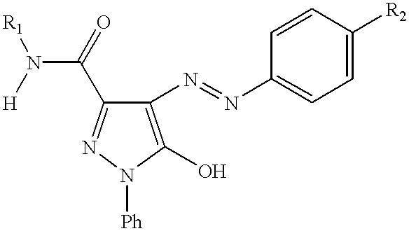
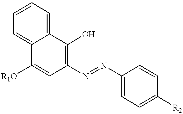
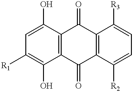
Numerous suitable combinations of specific dyes and thermal solvents which are suitable for use in accordance with the invention are shown in the Examples below.
In a preferred embodiment of the present invention, in the transfer material layer not more than 5% by weight of the material present in the layer should have a molecular weight higher than that of the highest molecular weight dye in the dye-containing phase. The presence of higher amounts of high molecular weight species, particularly polymeric species, results in undesirable, more viscous melts under imaging conditions which can adversely affect transfer of the imaging material to the receiver sheet. Further, this feature of the transfer material layer allows the layer to be coated from a solution which has a relatively low viscosity. It is preferred that the transfer layer include not more than about 2% by weight, and particularly preferably not more than about 1% by weight, of components having a molecular weight higher than that of the highest molecular weight dye in the dye-containing phase. Optimally, the thermal transfer material layer does not include any such higher molecular weight species.

Problems solved by technology

Further, if a microporous receiving sheet is not used, the durability of the image can be poor.
High energy input is not desirable in a portable printer or other imaging apparatus where energy usage can be a major concern, and high energy input per unit area can limit printing speed in a thermal head.
ng. This property is important in some instances such as variable dot printing, since a roughly gaussian temperature profile is produced over the area of a pixel and should the melted thermal transfer material have a viscosity which may be too high to completely penetrate the pores of the receiver material then there could be formed a relief image in dye at the edges of a dot giving rise to relatively lesser image durability and possibly affecting negatively the transfer of further dye materials in a multicolor sys

Method used


Image

  • Thermal transfer recording system
  • Thermal transfer recording system
  • Thermal transfer recording system

Examples


example 1

This example illustrates that a wide variety of commercially available and synthetic dyes can form a non-tacky, amorphous solid film suitable for use in the present invention. Commercially-available and custom-synthesized yellow, magenta, cyan and black dyes were screened for amorphous solid film formation in the following manner:

A 5% w / w solution of the test dye in 2-pentanone or 1-butanol was coated onto poly(ethyleneterephthalate) film base of 1.75 mil (44.5 .mu.m) thickness with a #6 Meyer rod. The coating was dried with warm air and tested after 24 hours for crystallization (using polarized light microscopy), abrasion resistance (using a rub test), and tack. The following materials showed no detectable crystallization and passed the rub and tack tests (which were carried out, respectively, by rubbing a cotton swab across the surface of the solid film and by touching with a finger the surface of the solid film).

Color Index (C.I.) Solvent Yellow 13, C.I. Solvent Yellow 19, C.I. S...

example 2

In this example, there is illustrated a combination of a dye which does not itself form a stable amorphous solid layer with a non-dye component to form an amorphous solid thermal transfer material layer according to the invention. In this example yellow dye (XXV) and magenta dye (XXVI), respectively, were combined with non-dye component 1,3-di(4-pyridyl)propane.

Yellow Dye XXV, whose preparation is described in Example 4 below, was a crystalline solid as determined by X-ray powder diffraction conducted as described above with reference to FIG. 2.

The combination of yellow Dye XXV and 1,3-di(4-pyridyl)propane (which melted at 61.2.degree. C. as a pure material) was prepared by dissolving both materials in tetrahydrofuran, removing the solvent by vacuum evaporation under mild heating to produce a transparent yellow solid. The Tg of various combinations of these components (measured as described in Example 5) is shown in Table I.

In none of these mixtures was any crystalline dye or crysta...

example 3

In this Example, the preparation of some representative thermal solvents used in the present invention is described. TS1 and TS2 were obtained from Aldrich Chemical Company and used as received. TS6 was prepared as described in Sasin et al., J. Am. Oil Chem. Soc. 34, 358 (1957).

TS3 (See also J.Am.Chem.Soc. 110, 5143 (1988)).

6.9 grams (30 mmoles) of the 1,12-dodecanedioic acid was added to 40 mL of thionyl chloride, and the resulting suspension stirred with heating to reflux. After 30 minutes reflux the mixture became clear; over the course of an additional 30 min at reflux a faint yellow color was noted. Much of the excess thionyl chloride was removed by distillation (collected 22 mL). The residual pale yellow oil was diluted with 1,2-dichloroethane (30 mL), and distillation was resumed until an additional 30 mL had been collected. The residual oil was diluted with dichloromethane (25 mL) and added dropwise with stirring at ca. -10.degree. C. (dry ice / IPOH bath) to a stirred mixture...


PUM

PropertyMeasurementUnit
melting pointaaaaaaaaaa

Abstract

There is described a thermal recording system which utilizes a donor element comprising a substrate and a thermal transfer material layer having a dye-containing phase which is amorphous and wherein the dye or dyes present in the amorphous phase form a continuous film. Imagewise heating of the medium transfers portions of the transfer layer to a receiver sheet, thus forming an image. The transfer layer may also include a non-dye phase comprising a thermal solvent. During the heating of the donor element, the crystalline thermal solvent melts and dissolves or liquefies at least a portion of the dye-containing phase, thereby lowering the temperature at which transfer of the transfer layer occurs.

Description

BACKGROUND OF INVENTIONThis invention relates to a thermal transfer recording system. More specifically, this invention relates to a thermal transfer recording system which utilizes a donor sheet in which the transfer layer contains an amorphous, or non-crystalline, dye phase.A number of different printing systems utilize thermal transfer of a dye from a donor sheet to a receiving sheet. A wide variety of specific mechanisms for thermal transfer have been used, but as described in "A New Thermal Transfer Ink Sheet for Continuous-Tone Full Color Printer", by M. Kutami et al., J. Imaging Sci., 1990, 16, 70-74, all fall into two broad categories. In the first of these, dyes thermally diffuse from a polymeric binder on the donor sheet into a second polymeric layer on the receiving sheet, in a process called "dye diffusion thermal transfer" (or D2T2; this process is also sometimes called "dye sublimation transfer"). In this type, only the dye is transferred, not the binder in which it is...

Claims


Application Information

Patent Timeline
Patent Type & Authority Patents(United States)
IPC IPC(8): C09D11/02B41M5/34B41M5/337B41J31/00B41M5/382B41M5/385B41M5/39B41M5/392B41M5/395B41M5/50B41M5/52G01D9/00
CPCC09D11/02B41M5/395B41M5/392B41M5/345B41M5/38207
Inventor ARNOST, MICHAEL J.BOUCHARD, ALAINDENG, YONGQIDOMBROWSKI, EDWARD J.GAUDIANA, RUSSELL A.HAQUE, SERAJULHASAN, FARIZA B.MARSHALL, JOHN L.TELFER, STEPHEN J.VETTERLING, WILLIAM T.VIOLA, MICHAEL S.
Owner INTELLECTUAL VENTURES I LLC
Learn More