Liquid crystal apparatus
a liquid crystal apparatus and liquid crystal technology, applied in the field of liquid crystal apparatus, can solve the problems of slow response speed, inability to follow high-speed motion display, and increase in the number of scanning signal lines,
- Summary
- Abstract
- Description
- Claims
- Application Information
AI Technical Summary
Problems solved by technology
Method used
Image
Examples
example 2
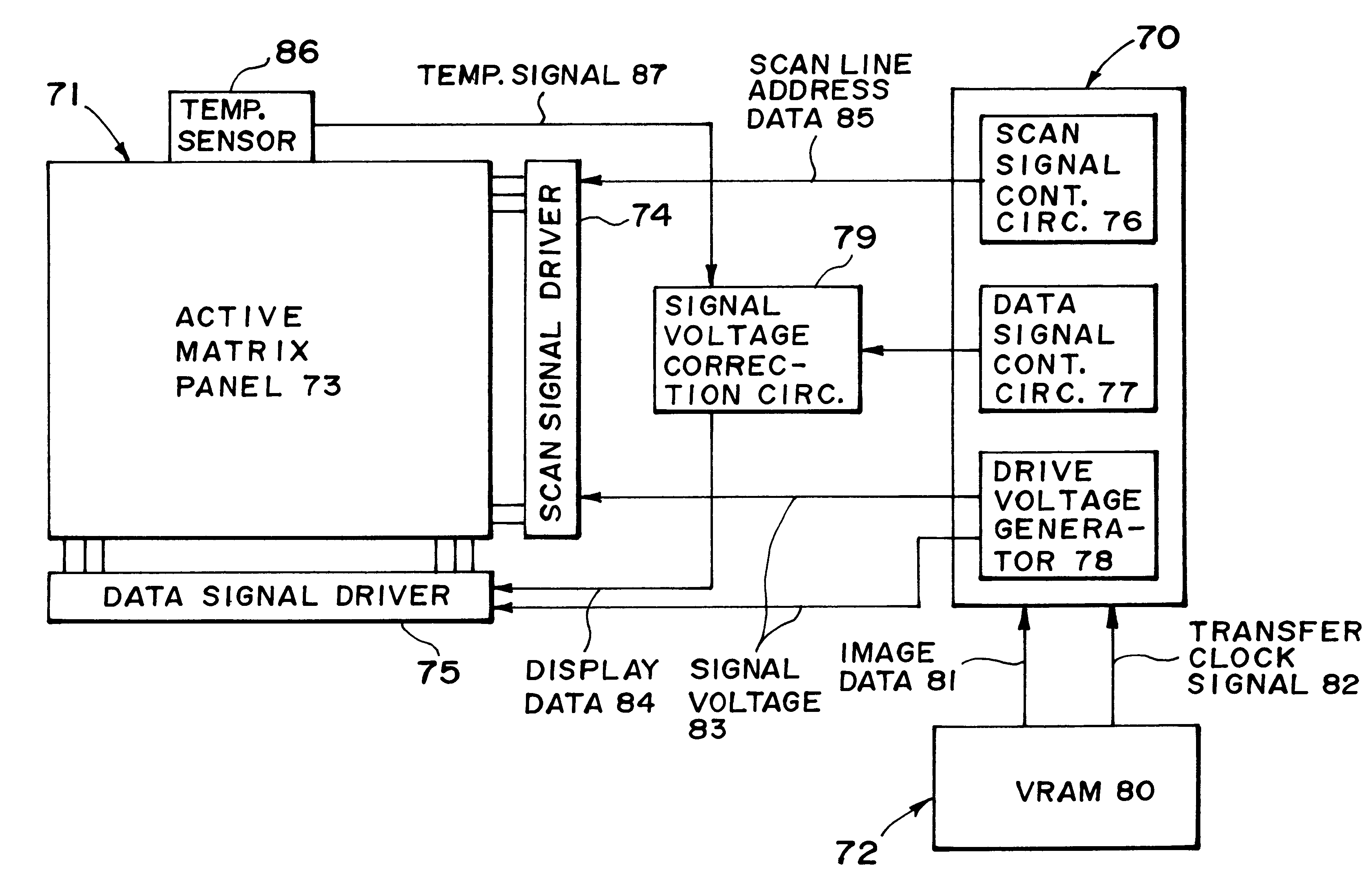
A liquid crystal apparatus was prepared in the same manner as in Example 1 except that the drive means (as shown in FIG. 7) was changed to that shown in FIG. 8 including a signal voltage correction circuit 79 as specifically show in FIG. 9.
The liquid crystal used (the same as in Example 1) showed the following temperature characteristic (dependence) of a spontaneous polarization (Ps), wherein the Ps was relatively linearly changed in an operation temperature range.
As apparent from above, the Ps value is increased on temperature decrease at a rate of ca. 0.5 (nC / cm.sup.2) per 1.degree. C., thus being represented by the following formula (5):
Ps (nC / cm.sup.2)=40+(1 / 2).times.(30-Z) (5),
wherein Z represents an operation temperature.
first embodiment
On the other hand, at the respective temperature, as is understood from the formulas (1), (3) and (3)' in First Embodiment described above, the voltage decrement .DELTA.V1 is always in proportion to .DELTA.Q (inversion amount of Ps).
In this example, the signal voltage correction circuit 79 as show in FIGS. 8 and 9 was designed and set so that a corrected data signal supplied therefrom was determined based on an additional (second) correction factor according to the formula (5) (temperature characteristic of Ps) in addition to the (first) correction factor according to the formula (4) (the voltage decrement correction by a transmittance), thus further accurately providing desired gradational levels.
According to this example, the signal voltage correction circuit 79 can provide a corrected voltage signal based on a first correction (voltage) signal sent from the data signal control circuit 77 and a second correction (temperature) signal set from the temperature sensor 86 in combinatio...
example 3
A liquid crystal apparatus was prepared in the same manner as in Example 1 except that the liquid crystal device (panel) was prepared by using the following materials and conditions:
.alpha.(Cs / Clc): 3,
Alignment film: aromatic polyimide film,
Spacer beads: 1.4 .mu.m dia.,
Liquid crystal composition: principally comprising pyrimidine skeleton-based liquid crystal compounds, and
Ps: 2.5 nC / cm.sup.2.
When the liquid crystal device was subjected to measurement of transmittance in combination with a pair of polarizers arranged to provide the darkest state under no voltage application by changing a source voltage while applying a DC voltage to gate lines, the resultant V-T characteristic was that shown in FIG. 3 with 0=3 (volts) and -V0=-3 (volts).
In this example, a maximum voltage decrement .DELTA.Vmax1 according to the above-mentioned formula (2) (in First Embodiment) was calculated as .DELTA.Vmax1=0.71 (V). Accordingly, a voltage decrement .DELTA.V1R for respective gradational levels due to...
PUM
 Abstract
Description
Claims
Application Information
 - R&D
- Intellectual Property
- Life Sciences
- Materials
- Tech Scout
- Unparalleled Data Quality
- Higher Quality Content
- 60% Fewer Hallucinations
Browse by: Latest US Patents, China's latest patents, Technical Efficacy Thesaurus, Application Domain, Technology Topic, Popular Technical Reports.
© 2025 PatSnap. All rights reserved.Legal|Privacy policy|Modern Slavery Act Transparency Statement|Sitemap|About US| Contact US: help@patsnap.com


