
Electromagnetic-wave shielding and light transmitting plate and panel laminated plate

Inactive Publication Date: 2002-10-22
BRIDGESTONE CORP
View PDF4 Cites 15 Cited by
  • Summary
  • Abstract
  • Description
  • Claims
  • Application Information

AI Technical Summary

Benefits of technology

It is an object of the present invention to solve the aforementioned problems and to provide an electromagnetic-wave shielding and light transmitting plate suitably used as an electromagnetic-wave shielding filter of a PDP which has good electromagnetic-wave shielding capability and good near infrared ray blocking capability, and having light transmitting capability so that distinct pictures are displayed.
It is another object of the present invention to provide a panel laminated plate in which a PDP is integrally bonded to an electromagnetic-wave shielding member to impart electromagnetic-wave shielding capability to the panel laminated plate itself, thereby lightening its weight, reducing its thickness, reducing the number of parts, and thus improving the productivity and reducing the cost and, further, to impart near infrared ray blocking capability in addition to the electromagnetic-wave shielding capability, thereby preventing the malfunction of a remote controller.
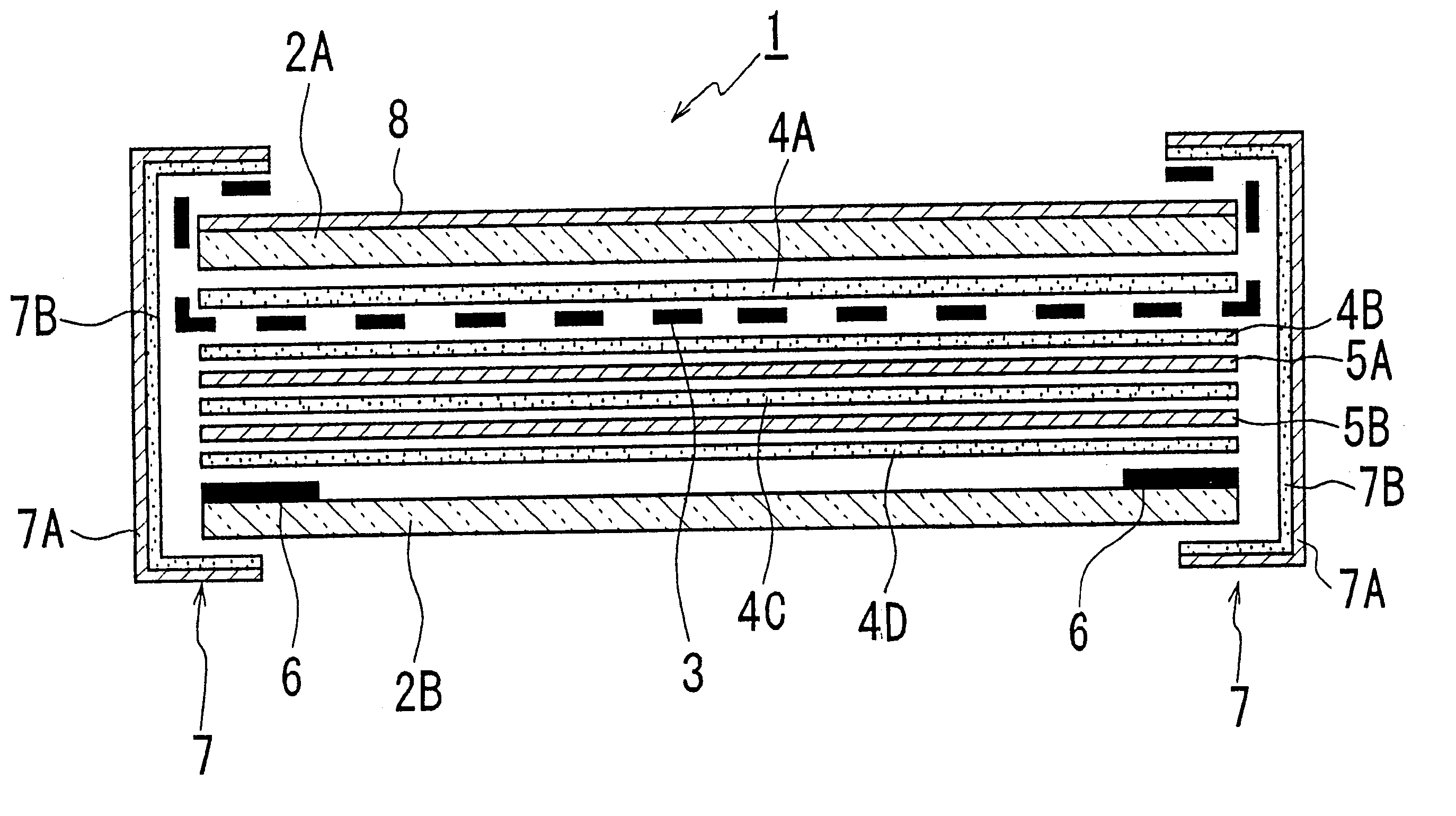
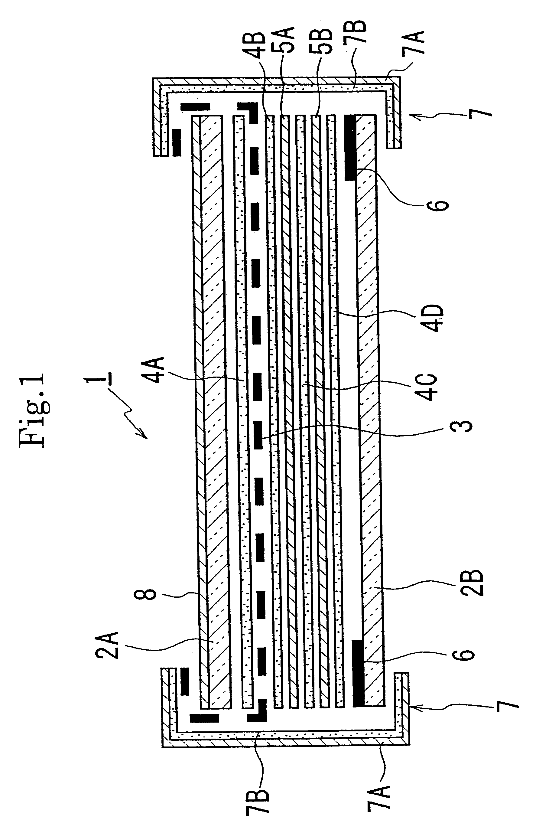
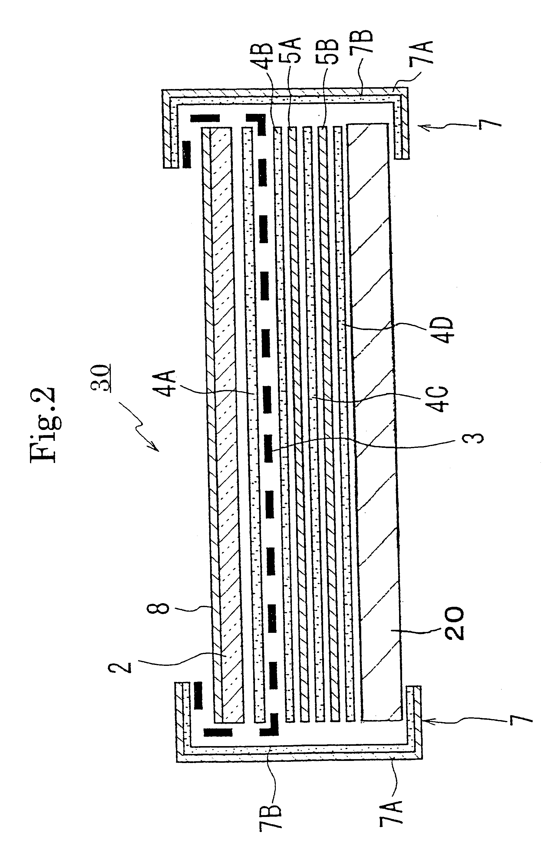
The electromagnetic-wave shielding and light transmitting plate of the present invention can obtain good electromagnetic-wave shielding capability and near infrared ray blocking capability because of the existence of the electromagnetic-wave shielding member and the near infrared ray blocking layer. In addition, since the near infrared ray blocking layer is composed of two or more of near infrared ray blocking layers and preferably of two or more of layer of different near infrared ray blocking materials, significantly improved near infrared ray blocking capability can be obtained by synergistic effect of the two or more of near infrared ray blocking layer.
The panel laminated plate of the present invention has the electromagnetic-wave shielding member and the near infrared ray blocking layer, thereby lightening its weight, reducing its thickness, reducing the number of parts, and thus improving the productivity and reducing the cost and, further the panel laminated plate can obtain good electromagnetic-wave shielding capability and near infrared ray blocking capability. In addition, since the near infrared ray blocking layer is composed of two or more of near infrared ray blocking layers and preferably of two or more of layers of different near infrared ray blocking materials, significantly improved near infrared ray blocking capability can be obtained by synergistic effect of the two or more of near infrared ray blocking layers.
In the present invention, a conductive mesh member made of metallic fibers and / or metal-clad organic fibers is preferably used as the electromagnetic-wave shielding member and when such a conductive mesh member is used, the safety is improved because the conductive mesh member prevents scattering of fragments when damaged.
When normal adhesives are used for the integration, there is a safety problem that fragments of the electromagnetic-wave shielding and light transmitting plate or the panel laminated plate are scattered when receiving an impact. However, since transparent elastic adhesives are used as the transparent adhesives, the scattering of fragments when damaged can be prevented, thereby improving the safety.

Problems solved by technology

With the spread of electronic appliances including office apparatuses and communication instruments, electromagnetic wave emission from these appliances has come into a problem.
That is, adverse effect of electromagnetic wave to the human body is feared and it is also a problem that the electromagnetic wave affects precision apparatus to cause malfunction.
1. Structure for disposing two panels is complicated.
2. As a transparent base plate made of glass or the like is required for each of the PDP and the electromagnetic-wave shielding transparent plate, the PDP and the electromagnetic-wave shielding transparent plate are made thicker and heavier in total.
3. The number of parts and labor are increased, thereby raising the cost.
However, the acrylic resin has a problem on the heat resistance, that is, the acrylic resin is poor at heat and thus may be deformed by heat.

Method used


Image

  • Electromagnetic-wave shielding and light transmitting plate and panel laminated plate
  • Electromagnetic-wave shielding and light transmitting plate and panel laminated plate
  • Electromagnetic-wave shielding and light transmitting plate and panel laminated plate

Examples


experimental example 1

A PET film of which thickness is 100 microns was employed as the base film. Each coating layers of near infrared ray blocking material was formed on one surface of the base film to have the following thickness.

In this manner, near infrared ray blocking films A, B, C were prepared.

Near infrared ray blocking film A: an alternative lamination of ITO and silver of which total thickness is 4000 .ANG.;

Near infrared ray blocking film B: a coating layer formed by a near infrared ray blocking material of immonium series with polyester binder to have thickness of 5 microns; and

Near infrared ray blocking film C: a coating layer formed by a near infrared ray blocking material of nickel complex series with acrylic binder to have thickness of 5 microns.

These near infrared ray blocking films A, B, C were laminated as shown in Table 1 to form laminated units. The light transmittance of each laminated unit in a range of near infrared ray was measured using a spectrophotometer. Based on the measured ...


PUM


Abstract

An electromagnetic-wave shielding and light transmitting plate is formed by two transparent base plates, a conductive mesh member, and a near infrared ray blocking film, wherein the conductive mesh member and the near infrared ray blocking film are interposed between the transparent base plates and are integrally bonded together. A panel laminated plate is formed by a transparent base plate, a PDP body, a conductive mesh member, and a near infrared ray blocking film, wherein the conductive mesh member and the near infrared ray blocking film are interposed between the transparent base plate and the PDP body and are integrally bonded together. Either in the above electromagnetic-wave shielding and light transmitting plate or in the panel laminated plate, the near infrared ray blocking film is a combination of two or more of near infrared ray blocking layers.

Description

BACKGROUND OF THE INVENTION AND RELATED ART STATEMENTThe present invention relates to an electromagnetic-wave shielding and light transmitting plate and a panel laminated plate of gas discharge type using a plasma display panel (hereinafter, referred to as "PDP") and, more particularly, to an electromagnetic-wave shielding and light transmitting plate suitable for a front filter of a PDP (plasma display panel), which has good electromagnetic-wave shielding capability and near infrared ray blocking capability. The present invention also relates to a panel laminated plate in which a PDP is integrated with an electromagnetic-wave shielding and light transmitting plate to impart electromagnetic-wave shielding capability to the panel laminated plate itself, thereby lightening its weight, reducing its thickness, reducing the number of parts, and thus improving the productivity and reducing the cost and, in addition, to impart near infrared ray blocking capability, thereby preventing the m...

Claims


Application Information

Patent Timeline
IPC IPC(8): H01J17/16H01J17/02H05K9/00
CPCH01J11/44H05K9/0096H01J2211/446
Inventor SAITO, SHINJIONO, SHINGOSUGIMACHI, MASATOYOSHIKAWA, MASATO
Owner BRIDGESTONE CORP
Learn More