Retinal stimulator

Inactive Publication Date: 2002-10-01
NEWSOUTH INNOVATIONS PTY LTD
View PDF15 Cites 869 Cited by
  • Summary
  • Abstract
  • Description
  • Claims
  • Application Information

AI Technical Summary

Benefits of technology

A Radio Frequency (RF) data and power trans-tissue, inductive link between the external image processor / encoder / transmitter and the internal receiver / decoder / stimulator provides for flexibility in the external image processing system such that future enhancements in processing techniques shall not require revision surgery or modification to the implanted receiver / decoder / stimulator and eliminates the need for maintenance of an internal power source such as a battery.
As chronic implantation requires, the apparatus is shaped in such a way as to provide comfort to the patient. All tissue contacting components and those components capable of exposure to tissue by way of leeching, etc. may be fabricated from materials known to be well tolerated by human tissue. Electronic circuitry required to power or control the apparatus is safely encapsulated within a hermetic chamber thereby protecting the patient from tissue-incompatible materials found in modem electronic components in addition to facilitating the presence of electronic circuitry within the corrosive environment of bodily fluids.
The circuitry of the receiver / decoder / stimulator possesses a means of excluding the delivery of a stimulation signal in the event that the encoded information received violates a pre-determined data protocol. This prevents erroneously encoded stimulus pulses from being delivered to the patient.
A common approach of insuring a charged balanced stimulus waveform in neural stimulation is to place a capacitor in series with each electrode such that no net DC current will pass. The present invention, in addition to using balanced, diphasic stimulus waveforms, employs a technique that reduces the quantity of capacitors necessary to insure charge balance from one capacitor per electrode to a total of two capacitors thus significantly reducing the size of the apparatus by reducing the quantity of components.
The apparatus possesses a means, external to the patient, of receiving data from the implanted receiver / decoder / stimulator such that the fall in electrical potential across the stimulation circuit may be derived. This, in addition to the programmable current amplitude shall facilitate the determination of the tissue impedance through which the stimulus has passed.

Problems solved by technology

Despite the progress achieved in Brindley and Lewin's studies, the useful quantity of phosphenes remained low.
Furthermore, the surgery required for implantation was extensive and the apparatus for stimulation large and cumbersome.
While stimulation of the visual cortex has shown promise, practicality remains an issue.
However, the mapping of stimuli is largely undefined.
As no functioning devices of this nature have been implanted in humans, the sufficiency of the incident light to generate the energy necessary to elicit a response in the retinal ganglion cells remains in question, as does the monophasic nature of the stimulus generated by photodiodes as this may cause electrode dissolution or nerve damage.
Thus, no technological changes to the system can be made without revision surgery.
It is likely that direct visual images are not the most effective means of utilizing a visual prosthesis as much of the normal processing of images cast upon a functional eye takes place in the lower orders of cells such as the photoreceptor, bipolar, amacrine and horizontal cells which are bypassed by these prostheses.

Method used


Image

  • Retinal stimulator
  • Retinal stimulator
  • Retinal stimulator

Examples


Embodiment Construction

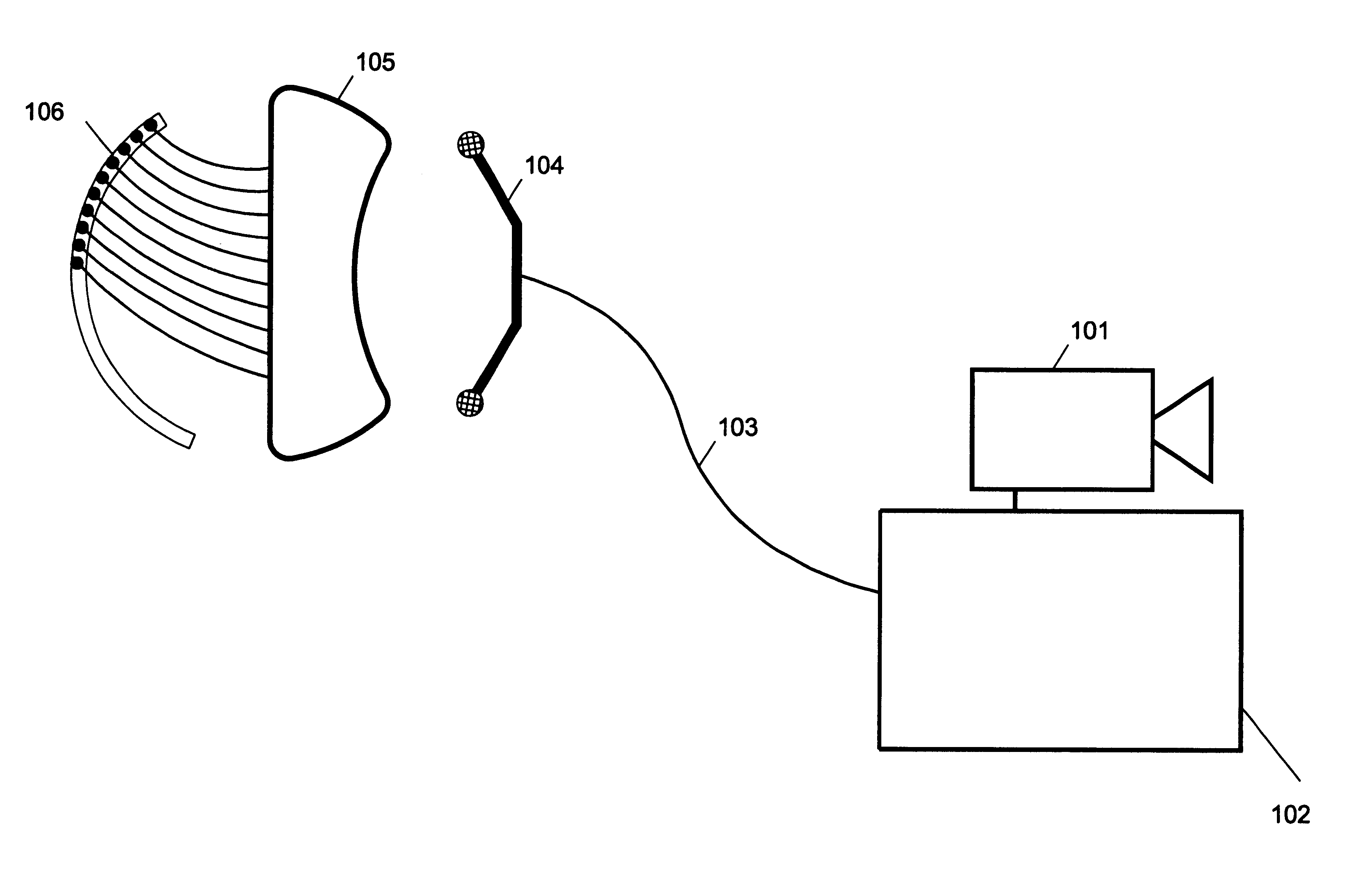
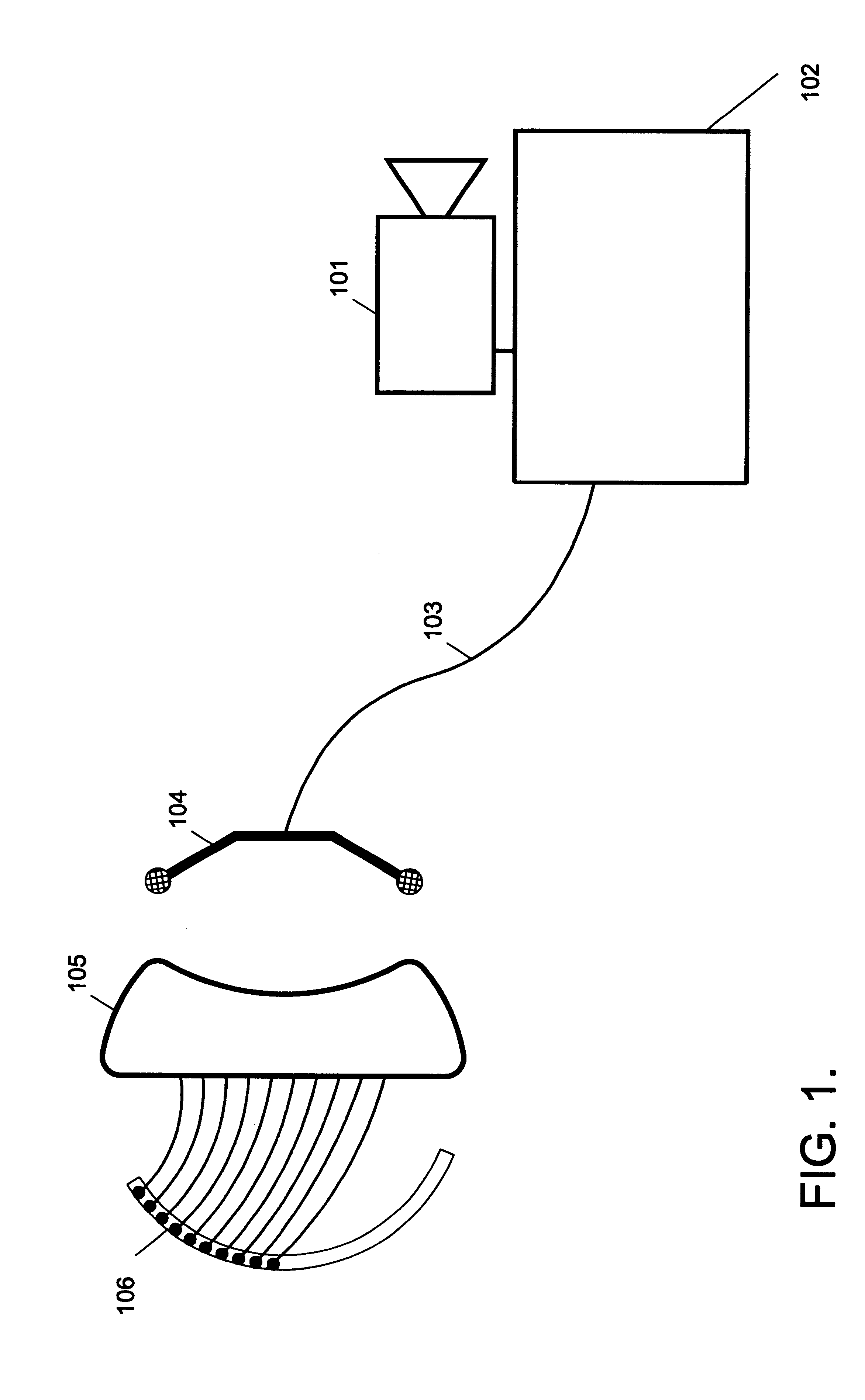
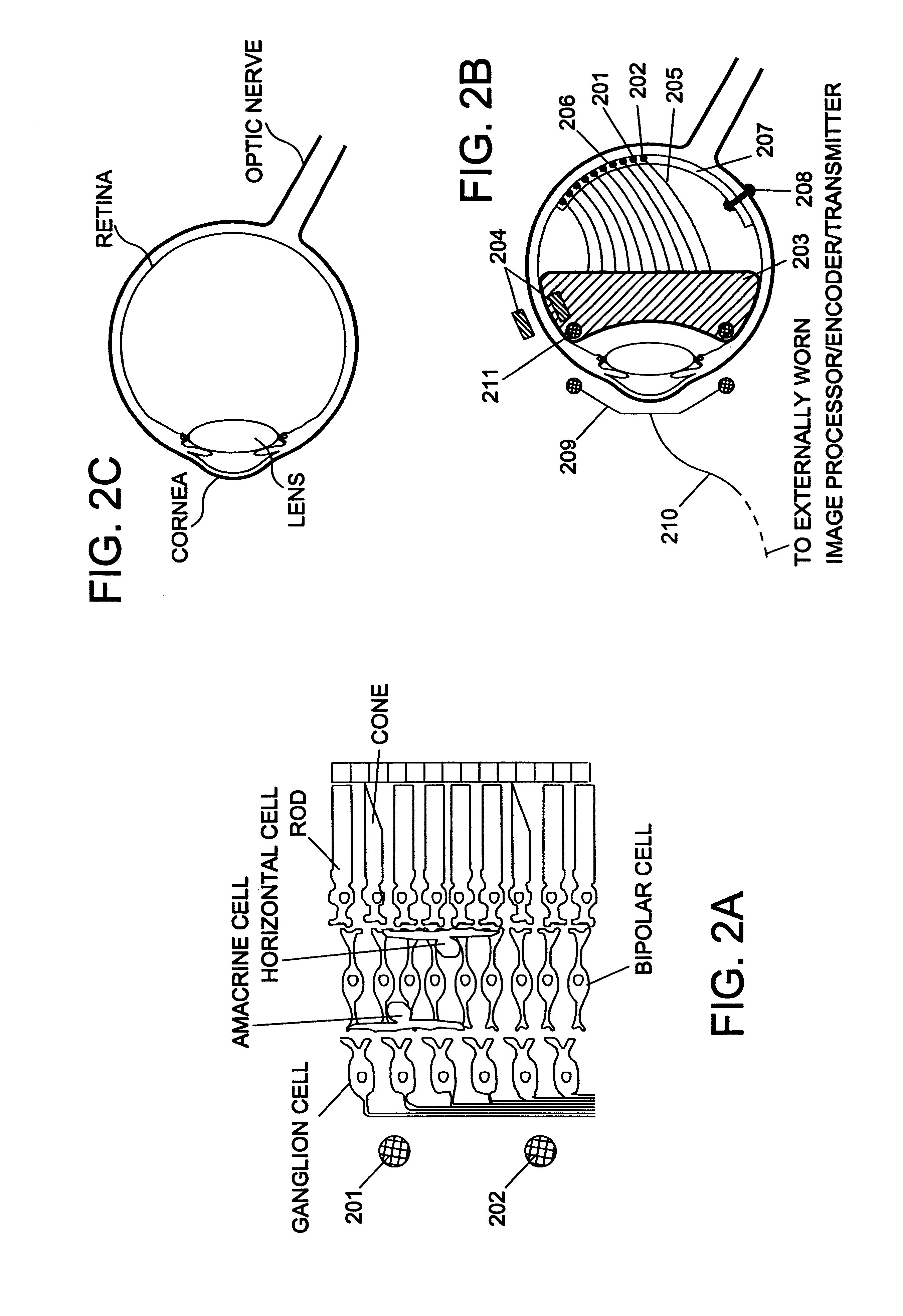
The method of the present invention, a retinal stimulator, is illustrated in FIGS. 1 through 11.

A retinal stimulator (FIG. 1) comprises an external image detector / processor 101 that supplies encoder / transmitter 102 with image data, said image data is translated into a series of encoded, radiofrequency bursts according to a pre-determined protocol and sent to tuned transmitting antenna 104 via cable 103; transmitted radiofrequency waves (not shown) are broadcast from antenna 104, through tissue (not shown), and received and decoded in receiver / decoder / stimulator 105 to extract stimulation parameter data and rectified to power said receiver / decoder / stimulator; in accordance with the decoded data, a controlled, diphasic, charge balanced, constant current stimulus wave is delivered to a single active stimulating electrode on electrode array 106, enters retinal tissue (not shown) and returns through one or more indifferent electrode(s) on 106 and to receiver / decoder / stimulator 105. If sp...


PUM


Abstract

An apparatus facilitating the delivery of electrical stimulation to physiologically excitable retinal nerve cells includes: (a), a receiver / decoder / stimulator comprising a semiconductor integrated circuit and other components hermetically sealed within a capsule, implanted and fixed within the eye of the patient such that it may receive power, and decode information from (b), an externally worn image processor / encoder / transmitter comprising an image detector, an image processor capable of translating the image into an array of discreet pixels of varying intensity, encoding the pixel information into a series of discreet data bursts representing the chosen current amplitude, pulse duration, stimulating electrode or electrodes, and reference electrode or electrodes, and transmitting this data to the receiver / decoder / stimulator through a tuned, inductive communication link such that the system may deliver controlled, charge balanced, diphasic, constant current stimulus pulses to (c), discreet metallic electrodes on a flexible, multiple site electrode array implanted on, near or under the surface of the retina. The apparatus provides for flexibility in the external image processing system such that future advancements in processing techniques shall not require revision surgery or modification to the implanted receiver / decoder / stimulator. Safeguards to protect the patient from the delivery of inappropriate stimulus are incorporated into the apparatus, and a method of external collection of diagnostic data from the implanted receiver / decoder / stimulator is described.

Description

The present invention concerns an apparatus for electrical stimulation of physiologically excitable retinal nerve cells.The invention described is primarily for an implantable retinal stimulator or visual prosthesis or bionic eye or artificial eye. That is, a system of components designed for the restoration of some visual faculties to the profoundly blind or severely vision impaired. The main objectives of the invention is to restore the differentiation between light and dark and to offer some visual input from the environment.In many patients who are blinded by degenerative conditions whereby the photoreceptors of the retina become dysfunctional, the retinal ganglion cells can remain largely in tact. It is the objective of the retinal -stimulator to by-pass the dysfunctional photoreceptors and electronically stimulate the surviving retinal ganglion cells, eventuating the perception of a spot of light or phosphene within the brain.The invention described herein comprises an implant...

Claims


Application Information

Patent Timeline
IPC IPC(8): A61N1/36A61N1/05A61F2/14
CPCA61N1/0543A61N1/36046A61F2/14
Inventor SUANING, GREGG J.O SLASHED.RGEN
Owner NEWSOUTH INNOVATIONS PTY LTD
Why Eureka
Try Eureka