
High-purity copper sputtering targets and thin films

a high-purity copper and target technology, applied in the direction of sputtering coating, vacuum evaporation coating, coating, etc., can solve the problems of reducing the specific resistivity of the element, the miniaturization of the element and the wiring, and the drawback of the greater specific resistivities, so as to achieve excellent thickness uniformity and low electric resistance

Inactive Publication Date: 2002-09-17
JX NIPPON MINING& METALS CORP
View PDF11 Cites 54 Cited by
  • Summary
  • Abstract
  • Description
  • Claims
  • Application Information

AI Technical Summary

Benefits of technology

It is an object of the present invention to provide copper sputtering targets capable of forming wiring deposition films having excellent thickness uniformity as well as the low electric resistance essential for high-speed operation elements and also provide such thin copper films.

Problems solved by technology

However, such materials are presenting problems including increased resistance value and electromigration of wirings due to the recent tendencies toward higher degrees of integration which results further miniaturization of elements and the wirings.
There have been some attempts to replace aluminum by a refractory metal such as molybdenum or tungsten, but their greater specific resistivities are a drawback.
Nevertheless, pure copper can hardly be employed as a wiring material because it easily oxidizes and is highly reactive with silicon and silicon dioxide films.
A major problem common to the abovementioned methods is an increase in electric resistance by the addition of another element.
An increased electric resistance retards signal transmission and adds to the power consumption.
However, the recent progress in device structures and barrier materials are altering the situation.
In reality, however, the past scanty research on wiring deposition of pure copper has given little impetus to the study of the conditions required of copper wiring material, specially as a material for sputtering target.

Method used


Image

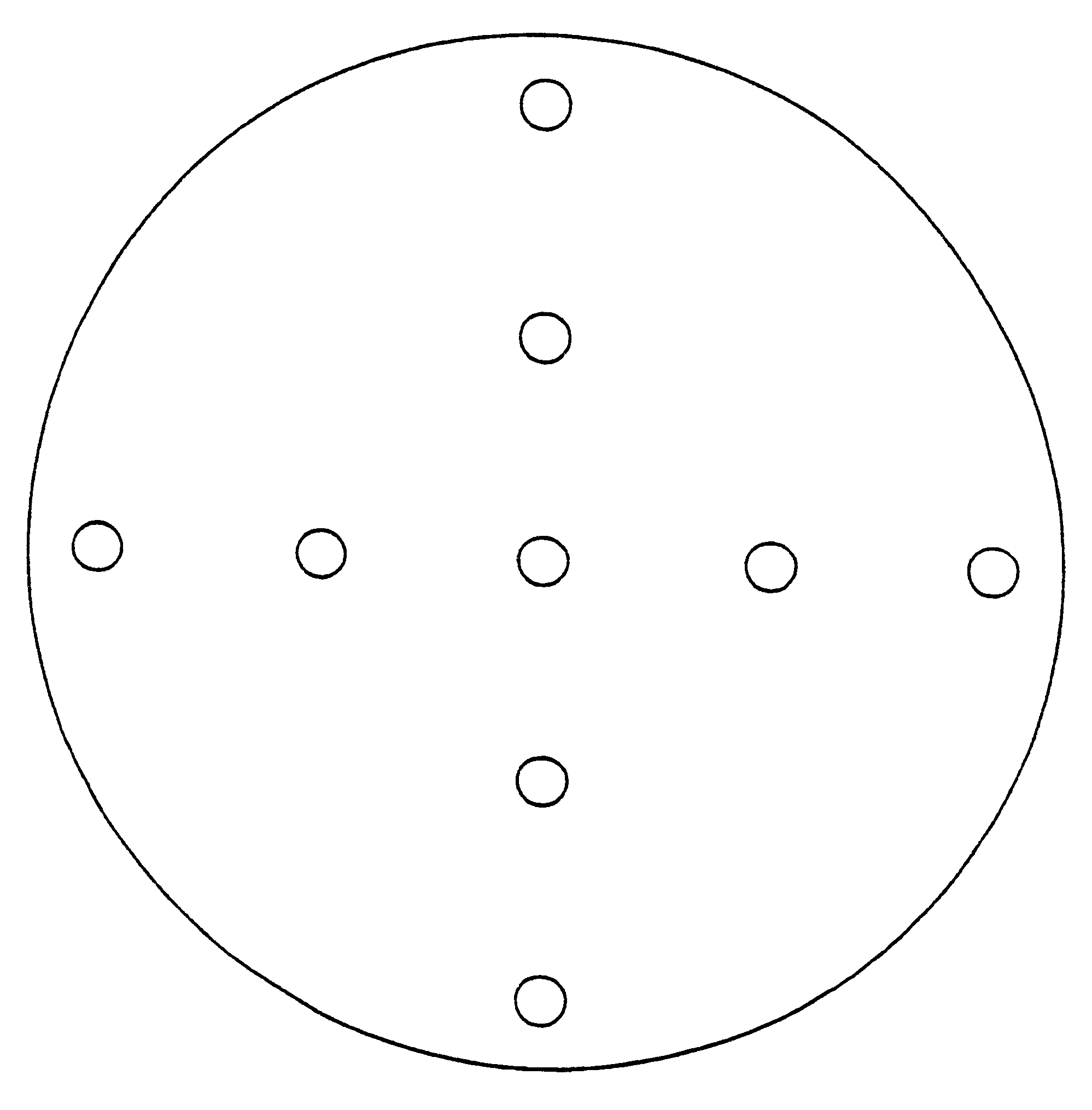
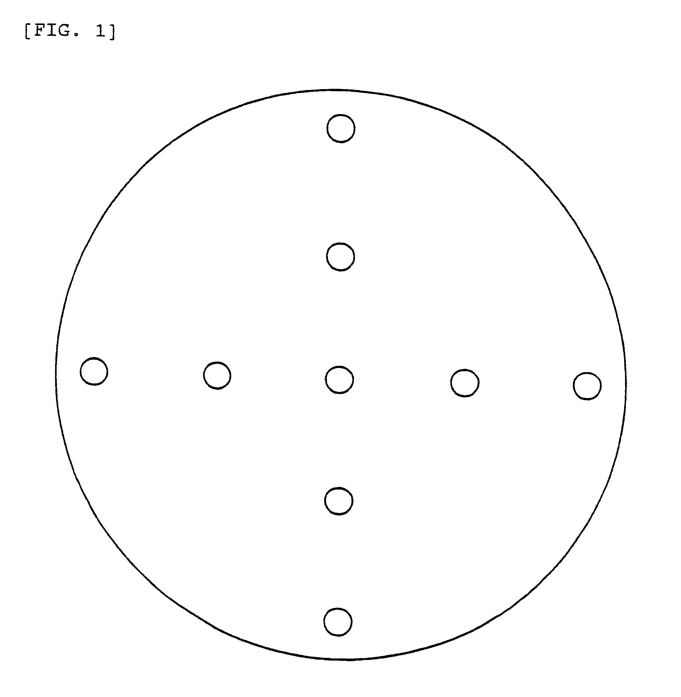
  • High-purity copper sputtering targets and thin films
  • High-purity copper sputtering targets and thin films

Examples


example 1

Target A

Electrolytic copper was electrorefined in a nitric acid bath with anode and cathode separated by a partition film and was vacuum melted to make a high-purity copper ingot (157 mm dia. and 60 mm thick). The ingot was heated to 600.degree. C. and hot forged to dimensions 190 mm dia. and 40 mm thick. It was again heated to 600.degree. C. and rolled to 265 mm dia. and 20 mm thick. Following this, it was cold rolled to 360 mm dia. and 10 mm thick and then heat treated at 400.degree. C. for one hour. The work was lathed to a disk shape 12.98 in. dia. and 6.35 mm thick, and the disk was bonded to a backing plate to complete a target. The conditions for lathing were: turning velocity, 70 rpm; depth of cut, 0.15 mm; and cutting tool feed, 0.12 mm.

example 2

Target B

The same ingot as used in Example 1 was hot rolled at 600.degree. C. to dimensions 300 mm dia. and 15 mm thick and then cold rolled to 360 mm dia. and 10 mm thick. The resulting plate was heat treated at 400.degree. C. for one hour, and under the same conditions as in Example 1, a target was made.

example 3

Target C

Starting with the ingot of Example 1, the process steps of Example 1 were followed down to cold rolling. The rolled plate was heat treated at 550.degree. C. for one hour and then subjected to the same machining conditions as in Example 1 to make a target.


PUM

PropertyMeasurementUnit
Fractionaaaaaaaaaa
Fractionaaaaaaaaaa
Fractionaaaaaaaaaa

Abstract

There is provided copper targets for sputtering capable of forming a deposition film with low electric resistance indispensable for high-speed operation elements and also with excellent thickness uniformity, and such thin copper films. A high-purity copper sputtering target is characterized by comprising up to 0.1 ppm each Na and K, up to 1 ppm each Fe, Ni, Cr, Al, Ca, Mg, up to 5 ppm each carbon and oxygen, up to 1 ppb each U and Th, and, excluding gaseous constituents, more than 99.999% copper. Preferably the average grain size on the sputter surface is 250 mum or below, with its dispersion thin plus or minus 20%. I(111) / I(200) of X-ray diffraction peak intensity on the sputter plane is at least 2.4 with its dispersion within plus or minus 20%.

Description

This invention relates to a high-purity copper sputtering target for the manufacture of thin film deposition materials on semiconductors as in large scale integration and relates also to a thin high-purity copper films of low resistivity obtained by sputtering with such high-purity copper sputtering target.Aluminum or aluminum alloy (e.g., silicon-containing aluminum) has commonly been used as a wiring material for semiconductor integrated circuits and the like. However, such materials are presenting problems including increased resistance value and electromigration of wirings due to the recent tendencies toward higher degrees of integration which results further miniaturization of elements and the wirings. There have been some attempts to replace aluminum by a refractory metal such as molybdenum or tungsten, but their greater specific resistivities are a drawback.Attempts have also been made to use copper in place of aluminum to take the advantage of its lower resistivity and great...

Claims


Application Information

Patent Timeline
IPC IPC(8): C23C14/34C23C14/18H01L21/02H01L21/285C23C14/14
CPCC23C14/185C23C14/3414H01L21/2855
Inventor TAKAHASHI, KAZUSHIGEKANO, OSAMU
Owner JX NIPPON MINING& METALS CORP
Learn More