
Work vehicle

a technology for working vehicles and trucks, applied in the field of vehicles, can solve the problems of outriggers adding to the complexity and expense of vehicles, and the vehicle has a tendency to tip,

Inactive Publication Date: 2002-06-25
TERRATOR CORP
View PDF46 Cites 56 Cited by
  • Summary
  • Abstract
  • Description
  • Claims
  • Application Information

AI Technical Summary

Benefits of technology

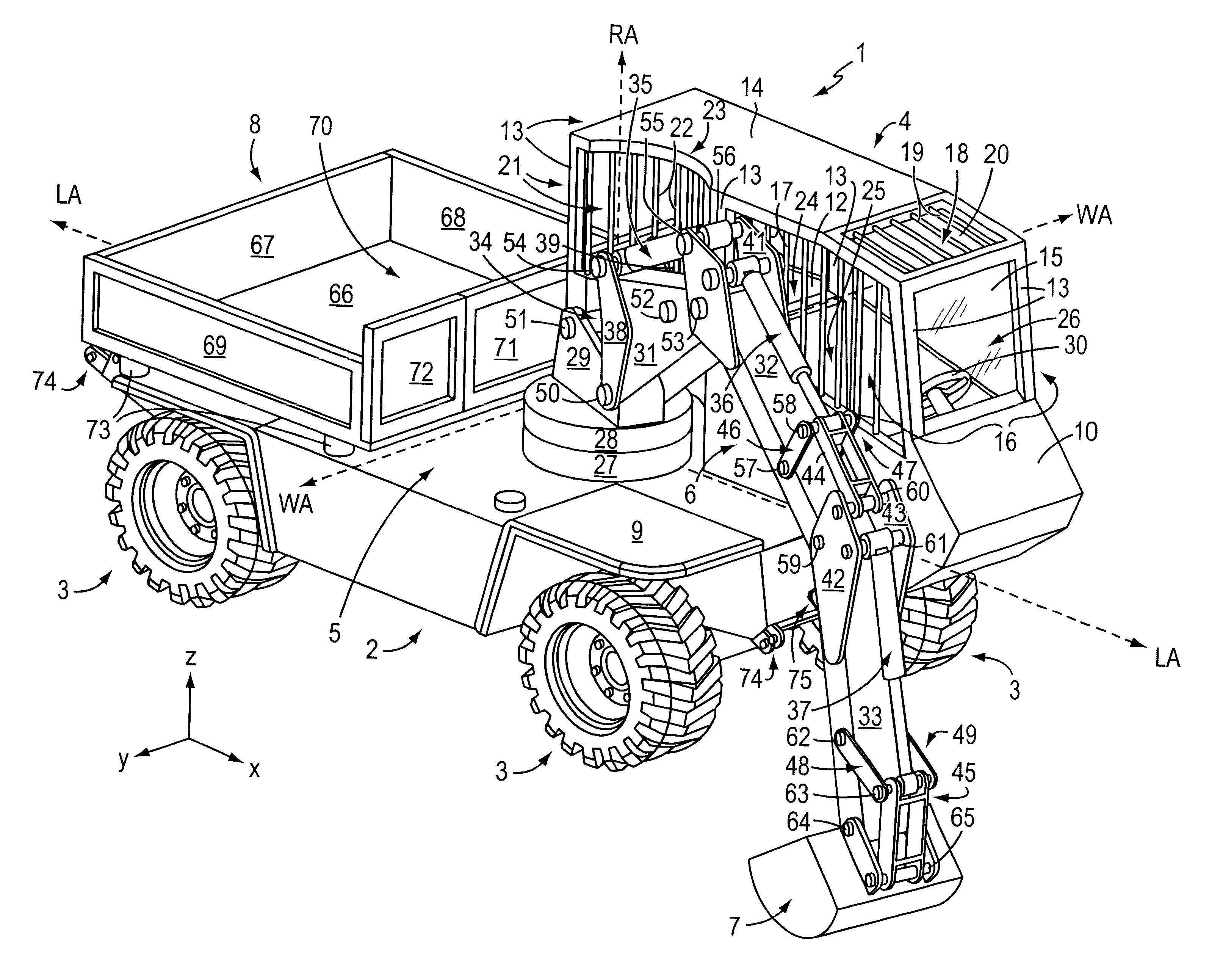
It is another object of the invention to provide a vehicle having a boom unit and coupled tool, that is configured for enhanced stability relative to previous vehicles and which requires no outriggers or other stabilizers for operation.
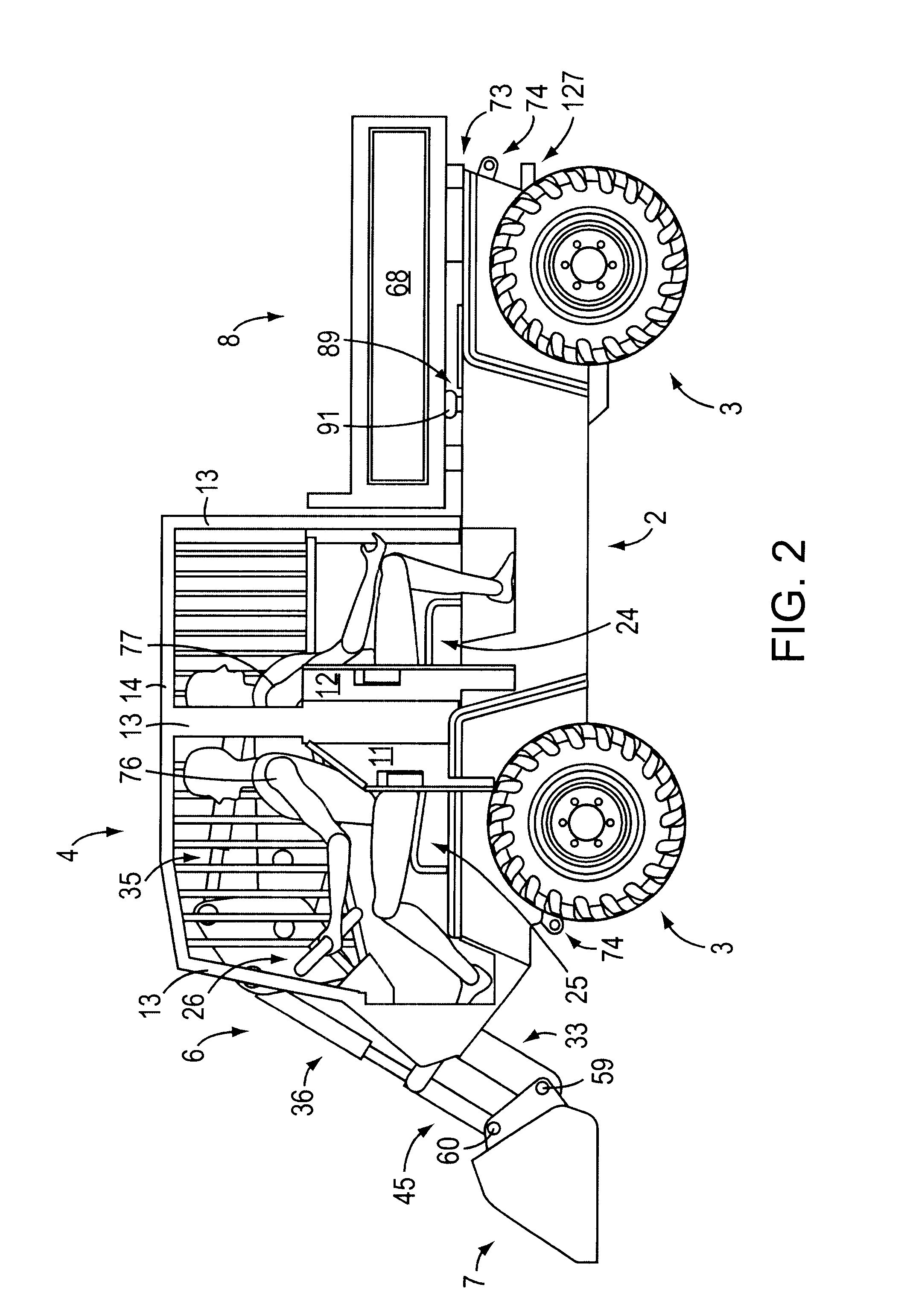
It is a further object of the invention to provide a vehicle with sufficient space for two persons, i.e., an operator and a co-operator, in which the co-operator can readily view the boom unit and attached tool as they are positioned over the vehicle's dump body to assist in operation and discharge of a load into the dump body in a relatively safe manner.
It is yet another object of the invention to provide a vehicle in which the boom unit and coupled tool can be stored in the vehicle's load body during travel to provide enhanced space for storage tanks on the vehicle sides as compared to previous vehicles.
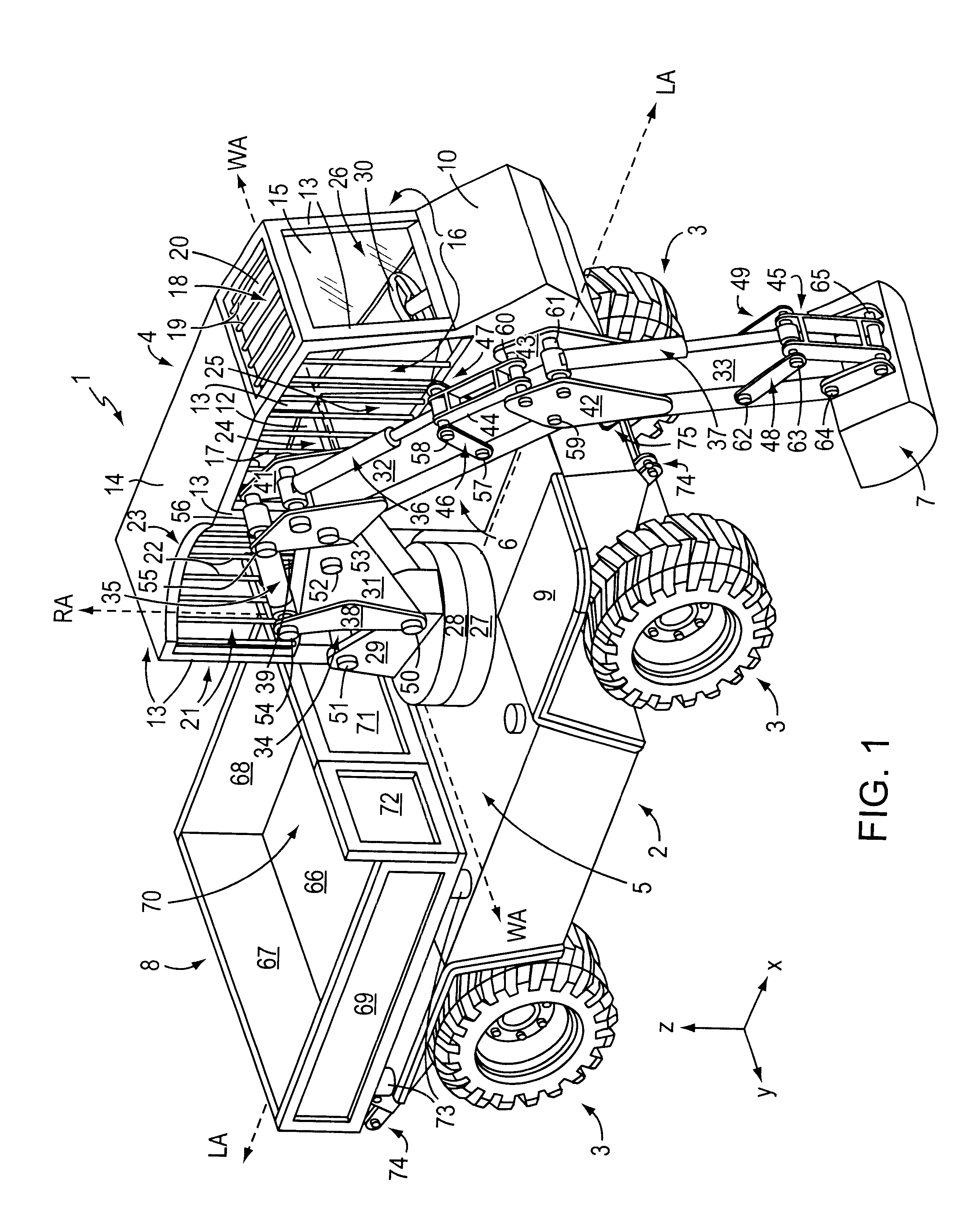
The vehicle of this invention includes a chassis, a cabin mounted on a first side of the chassis on a forward portion thereof, and a plurality of wheels coupled to the chassis to movably support the chassis on the ground. The vehicle also includes a boom unit mounted to the chassis adjacent the cabin, a tool coupled to an end of the boom unit, and a turntable unit mounted to the chassis at a central portion thereof. The boom unit is coupled to the turntable unit which supports the boom unit for rotation. The vehicle also includes a dump body mounted to a rear portion of the chassis. The turntable is capable of moving the boom unit and the tool over a second side of the chassis opposite the first side between a first position at which the tool is positioned forward of the chassis to pick up a load, and a second position at which the tool is positioned over the dump body to dump the load into the dump body. The boom unit can be adapted for coupling to different tools. For example, the tool can be a load bucket, a dipper bucket, an auger unit, a mower or a thresher. The vehicle can include at least one hanger member mounted to the chassis, which can be coupled to support the tool. The cabin can include a first seat for an operator of the vehicle and a second seat for a co-operator of the vehicle. The two seats can be positioned back-to-back to provide the co-operator with a clear view of the dump body and surrounding area to assist in moving the boom unit and tool to dump a load of earth, for example, into the dump body with accuracy. The dump body can be tilted relative to the chassis to discharge a load from the dump body. The dump body can be configured to dump the load from the rear end or on either side of the vehicle. The dump body can be configured with a floor portion surrounded by a front face, tailgate, and two side faces. A portion of the front face and the tailgate can be lowered to positions providing clearance for elongated load objects.

Problems solved by technology

Because the boom is coupled to the rail at the side of the cabin at a position well off-center with respect to the vehicle's center of gravity, the vehicle has a tendency to tip over.
Such outriggers add to the complexity and expense of the vehicle.
Such actions are difficult and strenuous for the operator, and present significant risk of a loss of control of the boom and tool and / or discharge of the load in an undesired location.
In addition, because the boom of U.S. Pat. No. 5,468,120 is positioned so far off-center on its vehicle, certain tools such as mowers cannot be attached to the boom because they require coupling to the vehicle along the direction of motive force applied by the vehicle.
Such adaptation blade, tools and hydropneumatic spring system add significant complexity and cost to the vehicle.
Furthermore, the vehicle of U.S. Pat. No. 5,468,120 is not equipped to transport relatively unwieldy loads such as logs, poles, bars, columns or other elongated objects.

Method used


Image

  • Work vehicle
  • Work vehicle
  • Work vehicle

Examples


Embodiment Construction

of Vehicle's Control Unit for the Turntable Unit, Boom Unit and Tool

In FIG. 6, the controller unit for the turntable unit 5, the boom unit 6, and the tool 7, is shown in further detail. As shown in FIG. 6, the vehicle 1 includes a control key switch 139 that is coupled via electrically-conductive line 140 to supply a control key signal to the controller 92. The control key switch 139 can be the ignition switch of the vehicle, for example, coupled to start the power plant 80 in addition to activating the controller 92 so that the turntable unit 5, the boom unit 6, and the tool 7 can be moved via respective hydraulic actuators under power supplied by the power plant. The controller 92 is activated to permit movement of the hydraulic actuators of the turntable unit 5, the boom unit 6, and the tool 7, based on the state of the control key switch signal. More specifically, the control key switch 139 generates an activated control key signal if the key of the vehicle 10 has been inserted ...


PUM


Abstract

The invented vehicle includes a chassis, a cabin mounted on a first side of the chassis on a forward portion thereof, and a plurality of wheels coupled to the chassis to movably support the chassis. The vehicle also includes a boom unit, a tool coupled to an end of the boom unit, and turntable unit mounted to the chassis at a central portion thereof, the turntable unit coupled to and supporting the boom unit for rotation relative to the chassis. The turntable unit is capable of moving the boom unit and the tool over a second side of the chassis opposite the first side between a first position at which the tool is positioned forward of the chassis to pick up the load and a second position at which the tool is positioned over the dump body to dump the load into the dump body. The vehicle also includes a dump body mounted to a rear portion of the chassis. The dump body can be tilted to the rear or either side of the vehicle. The tool attached to the boom unit can be a dipper bucket, a loader bucket, a mower, thresher or auger, for example. An accessory tool such as a mower can also be attached to the rear of the vehicle.

Description

1. Background of the InventionThe invention is directed to a vehicle capable of performing a wide range of tasks. For example, the vehicle can perform the functions of a tractor, bulldozer, dump truck, ditch digger, mower, and carrier. The versatility of the vehicle makes it effective for use in construction, landscaping, excavation, road work, farm and other work environments.2. Description of the Related ArtU.S. Pat. No. 5,468,120 issued Nov. 21, 1995 to Adolf Krob discloses a vehicle with four wheels, a driver's cabin mounted assymetrically on a front portion of the vehicle, a load container mounted to the rear portion of the vehicle, a working boom coupled to a rail at the side of the driver's cabin, and a tool attached to the end of the working boom. The rail extends from the front to the back of the cabin, and supports a rotary actuator to which the working boom is attached. To allow the boom to swing out in front or in back of the cabin, a rotary actuator coupled between the ...

Claims


Application Information

Patent Timeline
Patent Type & Authority Patents(United States)
IPC IPC(8): B62D21/18B62D33/06B60P1/04B60P1/16E02F9/08E02F9/16E02F3/04E02F9/20E02F3/06E02F9/24E02F3/38E02F3/96E02F3/28E02F3/30E02F3/18E02F3/36E02F9/22E02F3/42E02F3/32
CPCB60P1/167B62D33/0617E02F3/06E02F3/18E02F3/188E02F3/301E02F3/308E02F3/32E02F3/384E02F3/964E02F9/0808E02F9/163E02F9/2025E02F9/2275E02F9/24B62D21/186Y10S414/125
Inventor KORYCAN, GEORGEBELOHOUBEK, LIBOR
Owner TERRATOR CORP
Learn More