
Engine with dry sump lubrication, separated scavenging and charging air flows and variable exhaust port timing

a technology of dry sump lubrication and charging air flow, which is applied in the direction of crankcase compression engine lubrication, machines/engines, output power, etc., can solve the problems of direct injection of fuel into the cylinder, the system is difficult to acquire and maintain in a developing economy, and the kind of rich-lean combustion cannot be achieved in a conventional two-stroke engin

Inactive Publication Date: 2002-06-04
HARE NICHOLAS S
View PDF52 Cites 14 Cited by
  • Summary
  • Abstract
  • Description
  • Claims
  • Application Information

AI Technical Summary

Benefits of technology

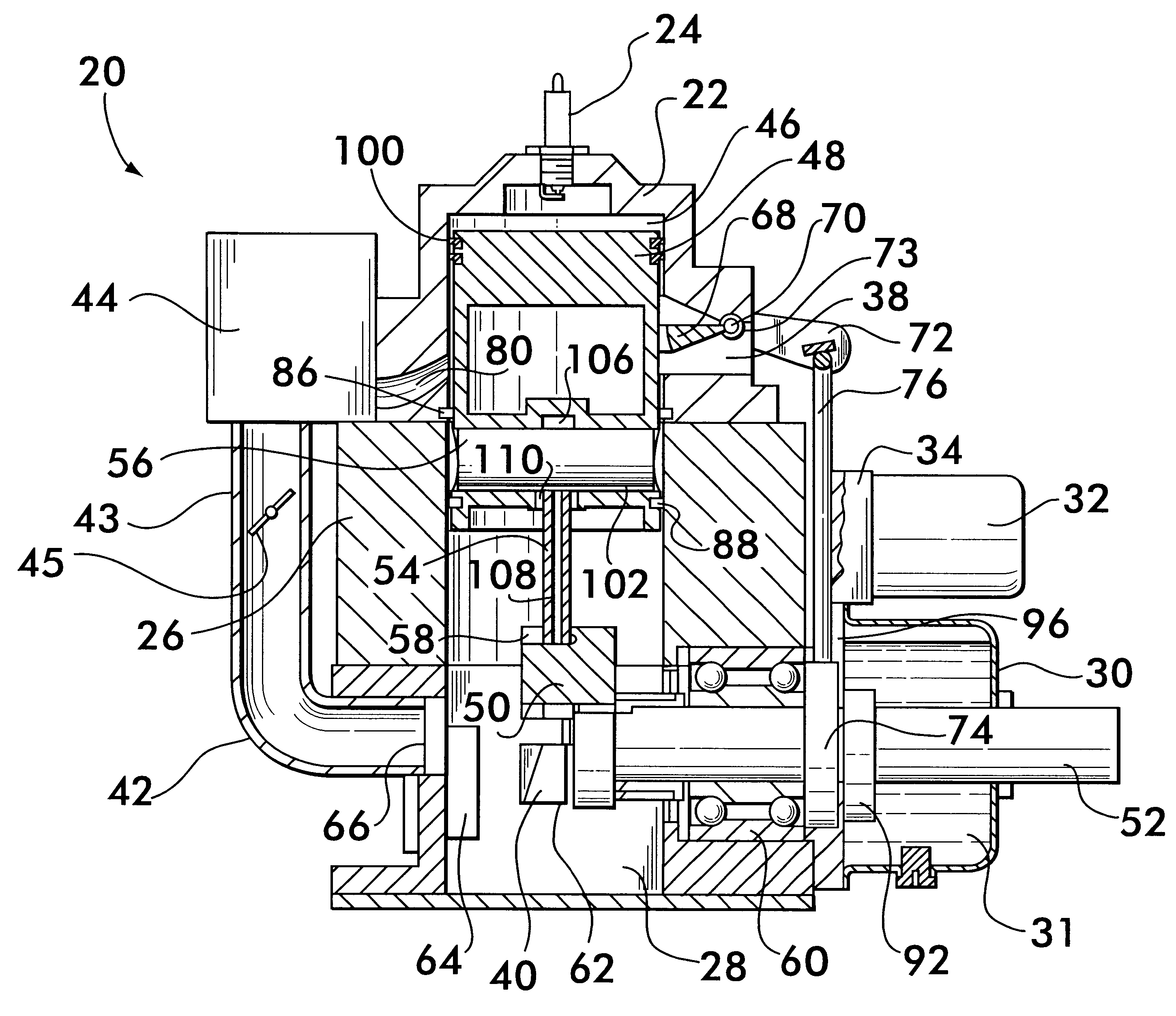
Nearly complete reduction in unburned fuel emission is achieved in the invention by separating the air flow from the crankcase to the cylinder into two separate tubes. One tube contains air only and scavenges the burned gas out of the cylinder through the exhaust port. The top of the port for this scavenging tube is located relatively high on the cylinder wall and is uncovered sooner on the piston down-stroke. The other tube contains air and fuel and charges the cylinder. The top of the port for the charging tube is located relatively lower on the cylinder wall and is uncovered later on the piston down-stroke than the scavenging tube port. This timing of the ports will allow the air-only scavenging flow time to purge the cylinder of burned gas before the air / fuel charge flow is initiated. Fuel will not be mixed with air on inlet to the crankcase, as is the case in conventional two-stroke spark-ignited engines, but rather is mixed on the passage from the crankcase to the cylinder through the charging tube. Fuel is mixed with air only on its passage through this charging tube and not on its passage through the scavenging tube.
By way of example only, the illustrated embodiment of the present invention addresses a single-cylinder, single main bearing, two-stroke, spark-ignited, loop-scavenged, over-square (bore to stroke ratio 2.38) engine of about 126 cubic centimeters gas displacement. However, the principles according to the invention of separated scavenging and charging tubes, charging tube fuel mixing, rich-lean combustion by arrangement of separated scavenging and charging tubes and ports, increased partial-load efficiency by throttling only a rich charging flow, variable exhaust port timing and piston-pumped distribution of lubricating oil in a dry-sump system have useful application in all other two-stroke, spark-ignited and compression-ignited engine types. The dry-sump lubricating system also has useful application in four-stroke engines in which a dry sump is advantageous, such as hand-held power tools and aircraft engines.

Problems solved by technology

This sort of rich-lean combustion cannot be achieved in a conventional two-stroke, spark-ignited engine.
This advantageous form of combustion is also achievable using advanced, direct-injected, two-stroke engine technology; however, direct injection of fuel into the cylinder is costly, and such a system would be difficult to acquire and maintain in a developing economy.
These reductions are achieved by partially blocking (throttling) the intake flow, leading to large pressure drops in the intake flow and reduced engine efficiency due to the piston-cylinder pumping power needed to overcome this pressure drop.
This advantage in engine efficiency is also achievable using advanced, direct-injected, two-stroke engine technology; however, direct injection is costly and would be difficult to acquire and maintain in a developing economy.

Method used


Image

  • Engine with dry sump lubrication, separated scavenging and charging air flows and variable exhaust port timing
  • Engine with dry sump lubrication, separated scavenging and charging air flows and variable exhaust port timing
  • Engine with dry sump lubrication, separated scavenging and charging air flows and variable exhaust port timing

Examples


Embodiment Construction

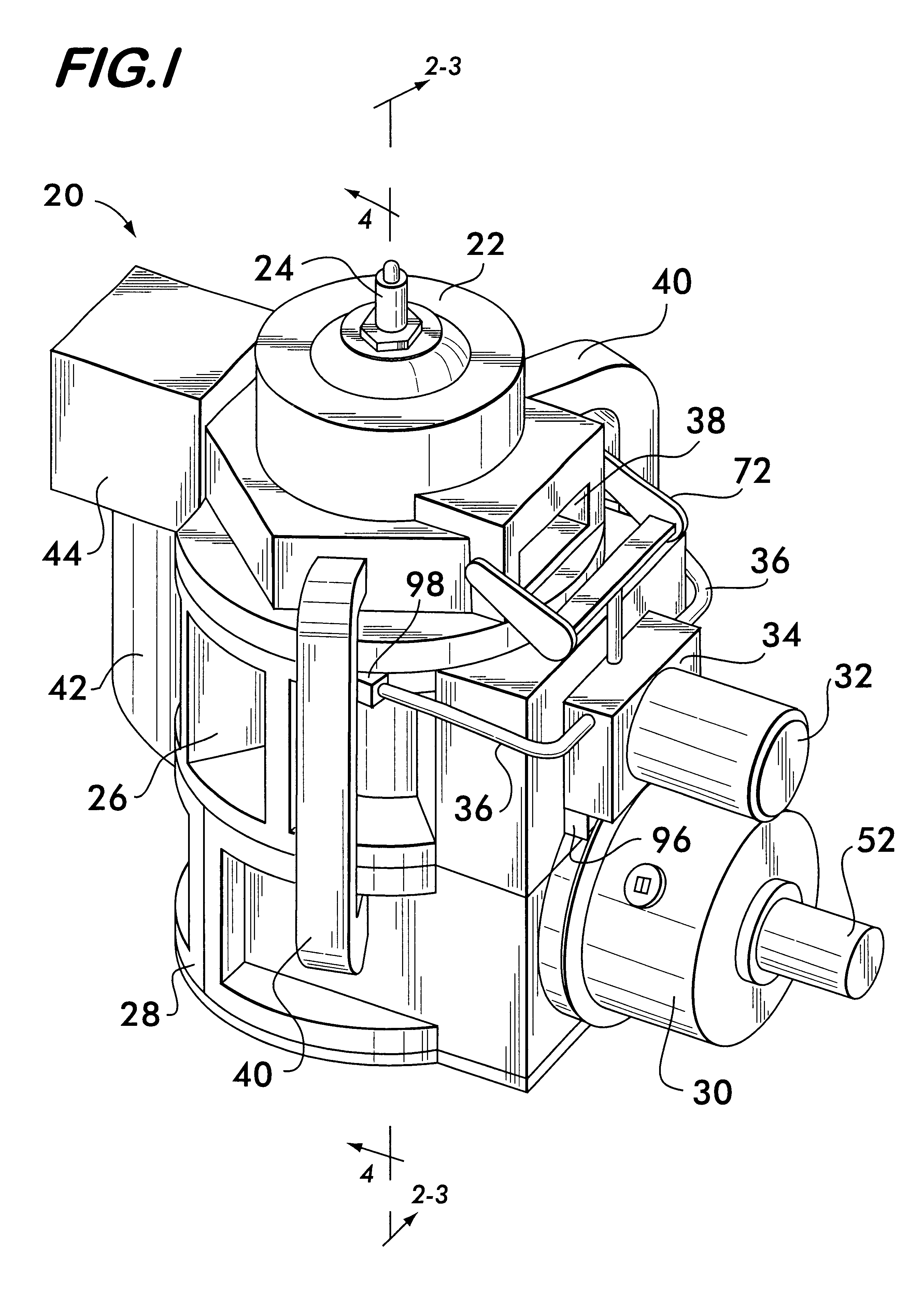
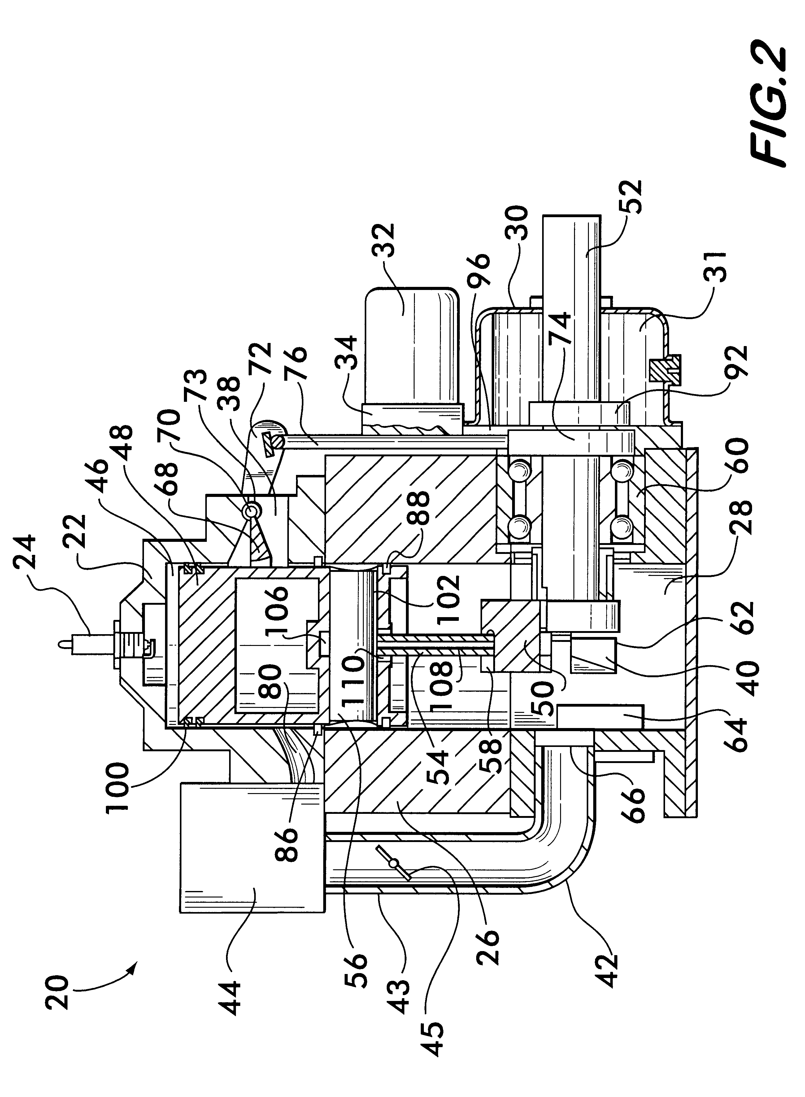
FIG. 1 shows an external view of an engine 20 according to the invention. Engine 20 comprises a cylinder 22 in which a spark plug 24 is mounted. An oil sleeve 26 is positioned immediately beneath the cylinder 22 and a crankcase 28 is attached to the oil sleeve. Preferably, an oil reservoir 30 for holding lubricating oil is mounted on crankcase 28. Associated with the oil reservoir are an oil filter 32, an oil distribution manifold 34 and oil lines 36 connecting the manifold 34 with the oil sleeve 26.

Also visible in FIG. 1 is an exhaust port 38 in cylinder 22, two scavenging tubes 40 which connect the crankcase 28 and the cylinder 22, a charging tube 42 and a fuel metering device 44. Charging tube 42 connects the crankcase to the fuel metering device 44 which supplies fuel to the cylinder 22 during engine operation. Fuel metering device 44 is preferably a carburetor but could also be a manifold fuel-injector system.

As shown in the sectional view of FIG. 2, cylinder 22 has a cylinder ...


PUM


Abstract

An engine is disclosed having an improved lubrication system and scavenging system. An oil sleeve is positioned between the cylinder and the crankcase, the sleeve having a bore sized to receive the piston. The piston and sleeve define an annular oil space which is connected to a reservoir by oil lines. A fixed seal is positioned surrounding the piston between the cylinder and the oil sleeve. A movable seal is mounted on and surrounds the piston. On the power stroke the movable seal moves away from the fixed seal, drawing oil from the reservoir into the annular oil space. On the compression stroke, the movable seal moves toward the fixed seal, forcing the oil from the annular oil space into the piston wrist pin and through conduits to the crank and main bearings and then back to the reservoir. Separate scavenging and charging tubes connect the crankcase to the cylinder.

Description

This invention relates to improved internal combustion engines, and especially to two-stroke engines having improved lubrication, scavenging, charging and exhaust port timing to reduce polluting emissions and improve engine performance and fuel efficiency.The present invention recognizes the global need for reduced hydrocarbon emissions from small power-producing engines, especially as relates to the rapidly growing demand for agricultural and light industrial power in developing economies. In these economies, the low weight and low cost of two-stroke engines will be difficult to ignore, and it may be expected that two-stroke engines will be widely used. Two-stroke engines have inherently high levels of unburned hydrocarbon emission due to their operating principle, in which burned exhaust gases are expelled from the engine's cylinder at the same time that a fresh fuel / air charge is brought in, leading inevitably to mixing between the two and inadvertent expulsion of unburned charge...

Claims


Application Information

Patent Timeline
IPC IPC(8): F01M3/02F02B75/16F01M3/00F02B75/00F01M1/06F02B75/02
CPCF01M1/06F02B75/16F01M3/02F02B2075/025
Inventor HARE, NICHOLAS S.
Owner HARE NICHOLAS S
Learn More