
Hydrofluoroether as a heat-transfer fluid

Inactive Publication Date: 2002-04-23
3M INNOVATIVE PROPERTIES CO
View PDF7 Cites 99 Cited by
  • Summary
  • Abstract
  • Description
  • Claims
  • Application Information

AI Technical Summary

Benefits of technology

The present invention provides a hydrofluoroether heat-transfer fluid which is inert, has good environmental and worker safety properties, has compatible electrical properties, is liquid over a wide temperature range, is essentially a single isomer or has a single empirical formula, and has good heat-trans

Problems solved by technology

However, each of these heat-transfer fluids has some disadvantage.
Water / glycol mixtures are temperature limited, that is, a typical low temperature limit of such mixtures is -40.degree. C.
Deionized fluids (water or water glycol) are limited to a high temperature of 80.degree. C. because this is the operating limit of commercially available deionizing beds.
However, this high temperature limit may be significantly lower if high electrical resistivity is desired because deionized fluids become quite corrosive.
Silicone oils and hydrocarbon oils are typically flammable.
Removing heat from electronic devices has become one of the most important obstacles to further improving processor performance.
As these devices become more powerful, the amount of heat generated per unit time increases.
Good electrical compatibility requires the heat-transfer fluid candidate to exhibit high dielectric strength, high volume resistivity, and poor solvency for polar materials.
In this application, heat-transfer fluid candidates are disqualified if their physical properties are not stable over time.
Each of these heat-transfer fluids has some disadvantage.
Silicone oils and hydrocarbon oils are typically flammable.
Each of these heat-transfer fluids has some disadvantage.
Liquid nitrogen systems offer limited temperature selectivity at the low temperature end.
Each of these heat-transfer fluids has some disadvantage.
Water / glycol mixtures are temperature limited, that is, a typical low temperature limit of such mixtures is -40.degree. C.
PFCs are non-flammable and are generally mechanically compatible with materials of construction, exhibiting limited solvency.
They do exhibit one important disadvantage, however, and that is long environmental persistence.
They also have the same major disadvantage, i.e., long environmental persistence.
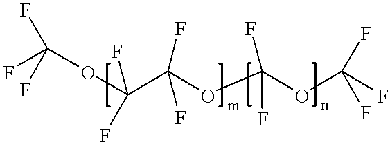
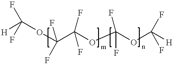
In addition, the methods developed for manufacturing these materials yield products that are not of consistent molecular weight and thus are subject to performance variability.
Thus, their physical properties may change over time which makes it difficult to predict performance.
However, these HFEs have relatively narrow liquid ranges and tend not to have boiling points over 100.degree. C.

Method used


Image

  • Hydrofluoroether as a heat-transfer fluid
  • Hydrofluoroether as a heat-transfer fluid
  • Hydrofluoroether as a heat-transfer fluid

Examples


example 1

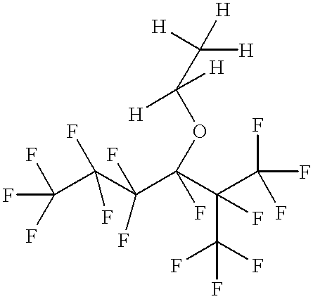
Preparation of n-C.sub.3 F.sub.7 CF(OC.sub.2 H.sub.5)CF(CF.sub.3).sub.2

Into a dry 600 milliliter Parr reactor were added 36.3 grams (0.625 mole) of anhydrous potassium fluoride and 108 grams of anhydrous diglyme (diethylene glycol dimethyl ether). The potassium fluoride was made by spray drying, was stored at 125.degree. C., and was ground shortly before use. The contents in the reactor were cooled with dry ice, then 125 grams (0.52 mole) of n-C.sub.3 F.sub.7 COF (approximately 90 percent purity) were added. When the reactor reached a temperature of 52.degree. C. and pressure of 65 psig (4190 torr), 101.5 grams (0.68 mole) of CF.sub.3 CF.dbd.CF.sub.2 (hexafluoropropylene) were added at 70.degree. C. and at a pressure range of 18-75 psig (1690-4640 torr) over approximately a three hour period, followed by a two hour hold period at 70.degree. C. The reactor and its contents were allowed to cool to room temperature, the reactor was opened, and to the reactor were added an additional 1....

example 2

Experiments were run to verify the pressure drop predictions of the theoretical model detailed above at -40.degree. C. The experimental apparatus is shown schematically in FIG. 4. The apparatus consists of an FTS Model RC-210B-20W chiller 52 connected with insulated polyethylene tubing 54 to a 1.35 meter length of 0.477 cm inner diameter copper tubing which is rolled into a thirty cm diameter coil 56. Holes (0.014 inch (0.0356 cm diameter)) drilled 1.04.+-.0.01 meters apart on the coil serve as static pressure taps. This leaves thirty-one pipe diameters upstream of the inlet static pressure taps and downstream of the outlet static pressure taps. These taps are connected to the ports of an Omega model XPC100DTH differential pressure transducer 58 (0-100 psid, .+-.0.5% of full scale). The mass flow through the coil is modulated with a manually-operated bypass valve 51. A 1 / 16" (0.16 cm) diameter type-J thermocouple 59 is installed in the inlet line just upstream of the coil such that ...

example 3

Freezing or pour points were measured for 3 related hydrofluoroether samples:

(1) n-C.sub.2 F.sub.5 CF(OC.sub.2 H.sub.5)CF(CF.sub.3).sub.2

(2) n-C.sub.3 F.sub.7 CF(OC.sub.2 H.sub.5)CF(CF.sub.3).sub.2

(3) n-C.sub.4 F.sub.9 CF(OC.sub.2 H.sub.5)CF(CF.sub.3).sub.2

The freeze and or pour points were measured by cooling a 1 ml sample contained in a double walled glass tube. The outer tube was sealed at both ends and had side ports for the addition of nitrogen gas. The inner tube was sealed at one end. The annular space between the tubes was purged with dry nitrogen and sealed. The sample was introduced into the inner tube and sealed with a septum. The temperature of the sample contained in the inner tube was monitored with an Omega Model DP-41 (available from Omega Engineering, Inc., Stamford, Conn.) resistance thermal device inserted into the fluid. The apparatus was lowered into the dewar flask of liquid nitrogen.

If the material froze to a white solid, a freezing point is reported. If inste...


PUM

PropertyMeasurementUnit
Temperatureaaaaaaaaaa
Heataaaaaaaaaa
Purityaaaaaaaaaa

Abstract

The present invention provides an apparatus comprising a device and a means for heat transfer comprising a hydrofluoroether heat-transfer fluid wherein the heat transfer fluid is 3-ethoxy-perfluoro(2-methylhexane). Another embodiment of the present invention is a method therefor.

Description

This invention relates to hydrofluoroether heat-transfer fluids. More particularly, this invention relates to 3-ethoxy-perfluoro(2-methylhexane) (n-C.sub.3 F.sub.7 CF(OC.sub.2 H.sub.5)CF(CF.sub.3).sub.2) as a heat-transfer fluid.Presently various fluids are used for heat transfer. The suitability of the heat-transfer fluid depends upon the application process. For example, some electronic applications require a heat-transfer fluid which is inert, has a high dielectric strength, has low toxicity, good environmental properties, and good heat transfer properties over a wide temperature range. Other applications require precise temperature control and thus the heat-transfer fluid is required to be a single phase over the entire process temperature range and the heat-transfer fluid properties are required to be predictable, i.e., the composition remains relatively constant so that the viscosity, boiling point, etc. can be predicted so that a precise temperature can be maintained and so t...

Claims


Application Information

Patent Timeline
IPC IPC(8): C09K5/00C09K5/10H01L21/66H01M8/04
CPCC09K5/10C07C19/08C07C43/12H01L21/67098
Inventor TOUSIGNANT, LEW A.TUMA, PHILLIP E.
Owner 3M INNOVATIVE PROPERTIES CO
Learn More