
Apparatus for producing deionized water

Inactive Publication Date: 2002-01-01
ASAHI GLASS CO LTD
View PDF6 Cites 22 Cited by
  • Summary
  • Abstract
  • Description
  • Claims
  • Application Information

AI Technical Summary

Benefits of technology

In the present invention, an ion exchanger comprises a first porous ion exchanger and a second porous ion exchanger. By using this ion exchanger, a specific amount of electric current can be applied at a low voltage and deionization can be carried out at a high level. Thus, by using the first porous ion exchanger and the second porous ion exchanger of the above mentioned compositions, moving distances of ion components can be shortened and dissociation of water can be fully carried out to achieve satisfactory deionization performances.
In accordance with a voltage gradient, ion components transfer through the same kind of ion exchange particles in contact with each other and move through a demineralizing compartment and permeate through a membrane to reach a concentrating compartment. Thus, in order to make the movement of ion components easy, it is preferable that the same kind of ion exchange resin particles are aligned in the direction of voltage. Like the first porous ion exchanger and the second porous ion exchanger, an ion exchanger, the same kind of ion exchange particles of which are continuously aligned to some degree in the direction of voltage, is preferable since ion components can transfer easily therethrough.
On the other hand, when dissociation of water occurs, protons and hydroxyl ions are generated to fully supply cations and anions without providing a bad influence on water quality, and this is preferable for improving ionization performances. In order to fully cause dissociation of water, it is important to make cation exchange resin particles in contact with anion exchange resin particles. Since the first porous ion exchanger and the second porous ion exchanger have oppositely ionized ion exchange resin particles made in contact with each other in the inside to some extent, dissociation of water can be fully caused.

Problems solved by technology

However, this method has problems that a troublesome operation is required and that a waste liquid of the acid or alkali used for the regeneration, is discharged.
However, a purity of deionized water was not stable due to such problems that ion exchangers having the same ionic charges were aggregated each other, that ion exchange resin particles or fibers were damaged by a water stream and that efficient demineralization and regeneration could not be conducted.
According to these methods, an ion exchanger is fixed, but these methods have various defects that it is necessary to use radiation, that a step of making composite fibers is complicated, and that a mechanical strength is not always satisfactory.

Method used


Image

  • Apparatus for producing deionized water
  • Apparatus for producing deionized water

Examples


example 1

A sulfonic acid type cation exchange resin (Diaion SK1B: tradename manufactured by Mitsubishi Chemical Corporation) having an average particle size of 620 .mu.m and an ion exchange capacity of 4.2 meq / g dry resin and a quaternary ammonium salt type anion exchange resin (Diaion SA10A: tradename manufactured by Mitsubishi Chemical Corporation) having an average particle size of 540 .mu.m and an ion exchange capacity of 3.7 meq / g dry resin were dried and mixed in a ratio of cation exchange resin / anion exchange resin of 50 / 50 (volume ratio in dry state) to prepare a mixture having an ion exchange capacity ratio of 60 / 40.

3 wt % of a linear low density polyethylene (Affinity SM-1300: tradename manufactured by Dow Chemical Company) was mixed with the above prepared mixture, and the mixture was kneaded at 120 to 130.degree. C. The kneaded material thus obtained was heat-formed by a flat plate press at 130.degree. C. to obtain a sheet-like porous ion exchanger having a thickness of 6 mm.

A ca...

example 2

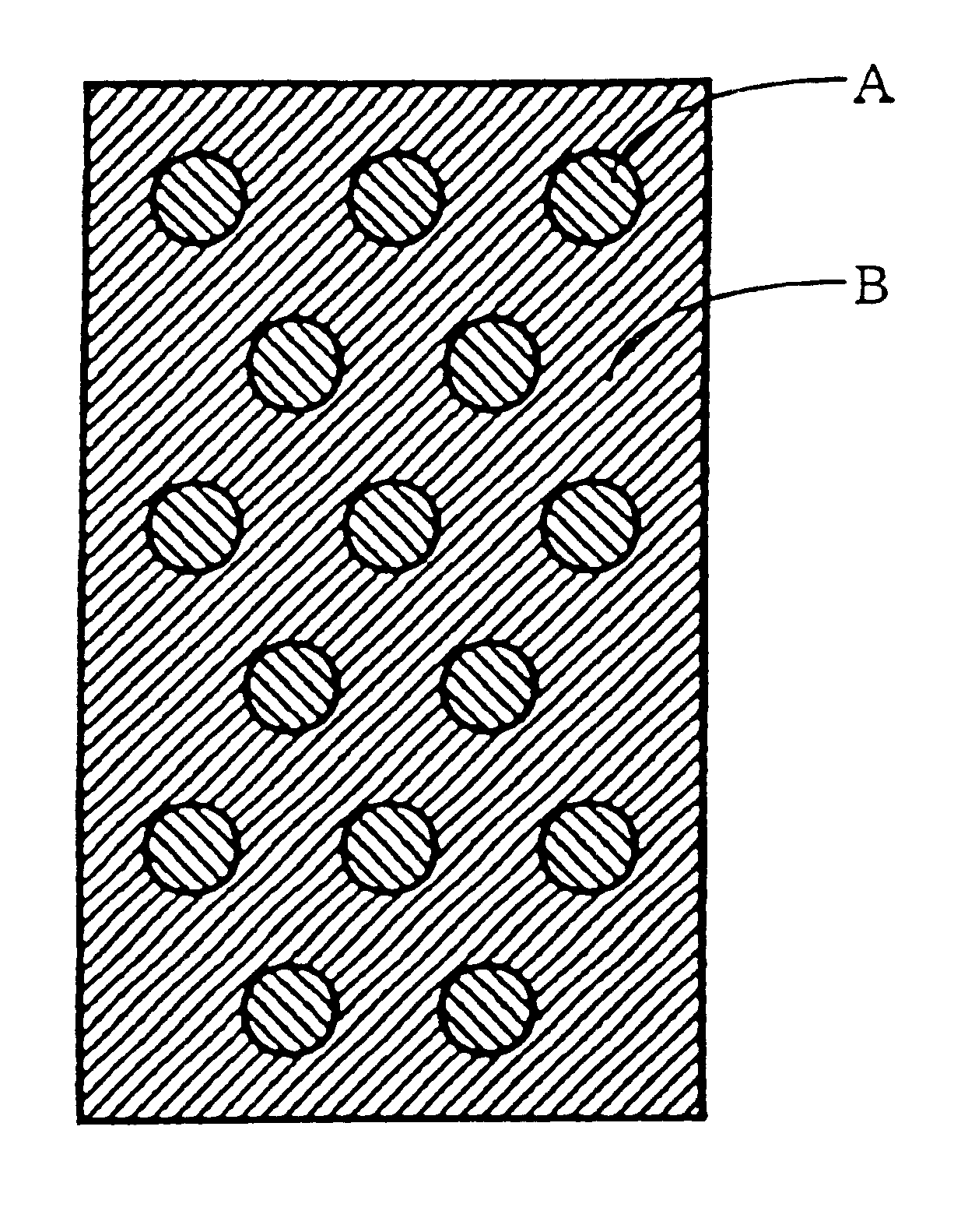
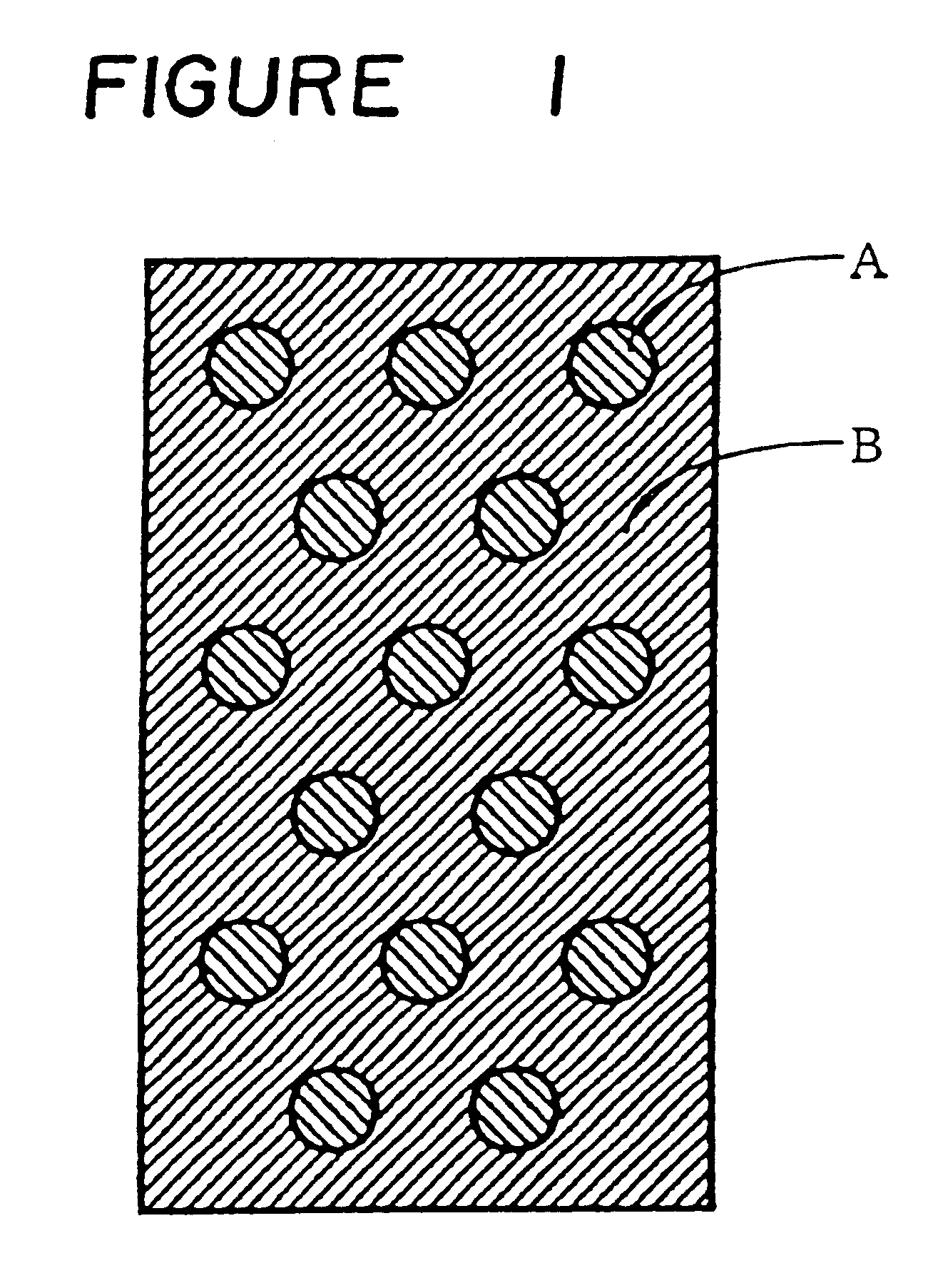
The same cation exchange resin and anion exchange resin as used in Example 1 were respectively dried, and 3 wt % of a linear low density polyethylene (Affinity SM-1300: tradename manufactured by Dow Chemical Company) was mixed with each of the above ion exchange resins, and each mixture was kneaded at 120 to 130.degree. C. Thereafter, each of the kneaded cation exchange resin and the kneaded anion exchange resin was heat-formed by a flat plate press at 130.degree. C. to obtain a sheet-like cation exchanger A having a thickness of 6 mm and a sheet-like anion exchanger B having a thickness of 6 mm. Thereafter, the cation exchanger A and the anion exchanger B were punched, and the punched disk-like cation exchanger A having a diameter of 2 cm was fixed into the punched anion exchanger B in such a manner as illustrated in FIG. 1 to prepare a porous ion exchanger having a dot-like pattern.

Each sheet of the above prepared porous ion exchangers was accommodated in each of the demineralizin...

example 3

The same ion exchange resins as used in Example 1 were dried, and the dry cation exchange resin and the dry anion exchange resin were mixed in a weight ratio of 8 / 2 (cation exchange resin / anion exchange resin), and a sheet-like first porous ion exchanger was prepared in the same manner as in Example 1. Thereafter, an anion exchange resin and a cation exchange resin were mixed in a weight ratio of 8 / 2 (anion exchange resin / cation exchange resin), and a sheet-like second porous ion exchanger was prepared in the same manner as in Example 1. Thereafter, by using the above prepared two porous ion exchangers, a porous ion exchanger having such a dot-like pattern as shown in FIG. 1 was prepared in the same manner as in Example 2.

Each sheet of the above ion exchangers was accommodated in each demineralizing compartment in the same electrodialyzer as used in Example 1, and water is supplied to swell the above ion exchangers to adjust a pressure in a gap to an ion exchange membrane to about 2...


PUM

PropertyMeasurementUnit
Weightaaaaaaaaaa
Weightaaaaaaaaaa
Equivalent per massaaaaaaaaaa

Abstract

An apparatus for producing deionized water, which has an ion exchanger accommodated in demineralizing compartments of an electrodialyzer having cation exchange membranes and anion exchange membranes alternately arranged between an anode and a cathode, wherein the ion exchanger is a composite ion exchanger comprising a first porous ion exchanger having a mixture of 60 to 95 wt % of cation exchange resin particles and 5 to 40 wt % of anion exchange resin particles bonded to each other and a second porous ion exchanger having a mixture of 60 to 95 wt % of anion exchange resin particles and 5 to 40 wt % of cation exchange resin particles bonded to each other.

Description

Field of the Inventionpresent invention relates to an apparatus for producing deionized water.DESCRIPTION OF THE BACKGROUNDHeretofore, as a method for producing deionized water, it is common to obtain deionized water by passing water to be treated through a bed packed with an ion exchange resin so that impurity ions are removed as adsorbed on the ion exchange resin. Here, it is common to employ a method of regenerating the ion exchange resin having its ion-exchanging and adsorbing abilities lowered, by means of an acid or alkali. However, this method has problems that a troublesome operation is required and that a waste liquid of the acid or alkali used for the regeneration, is discharged. Therefore, a method for producing deionized water which requires no such regeneration, is desired.From such a viewpoint, a self-regenerating type electrodialysis deionizing method using a combination of an ion exchange resin and an ion exchange membrane has been recently noted. This method employs...

Claims


Application Information

Patent Timeline
IPC IPC(8): B01J47/00B01J47/08B01D61/48B01D61/42C02F1/469C02F1/42
CPCB01D61/48B01J47/08C02F1/469C02F1/42
Inventor IWAMOTO, JUNJIRO
Owner ASAHI GLASS CO LTD
Learn More