
Distortion control feedback loop utilizing a non-linear transfer function generator to compensate for non-linearities in a transmitter circuit

a non-linear transfer function and feedback loop technology, applied in the direction of negative-feedback circuit arrangement, amplifier modification to reduce non-linear distortion, transmission, etc., can solve the problem of less-than-desirable response characteristics of the feedback loop, power amplifiers typically have non-linear transfer functions, and the loop response may be slower than desired

Inactive Publication Date: 2001-11-20
SKYWORKS SOLUTIONS INC
View PDF7 Cites 39 Cited by
  • Summary
  • Abstract
  • Description
  • Claims
  • Application Information

AI Technical Summary

Benefits of technology

Likewise, a tuning device can be implemented to adjust the output of the linear function generator. Similarly, in embodiments operating on current, the tuning device controls the amount of current shunted to ground, thereby controlling the output level of the linear function generator.

Problems solved by technology

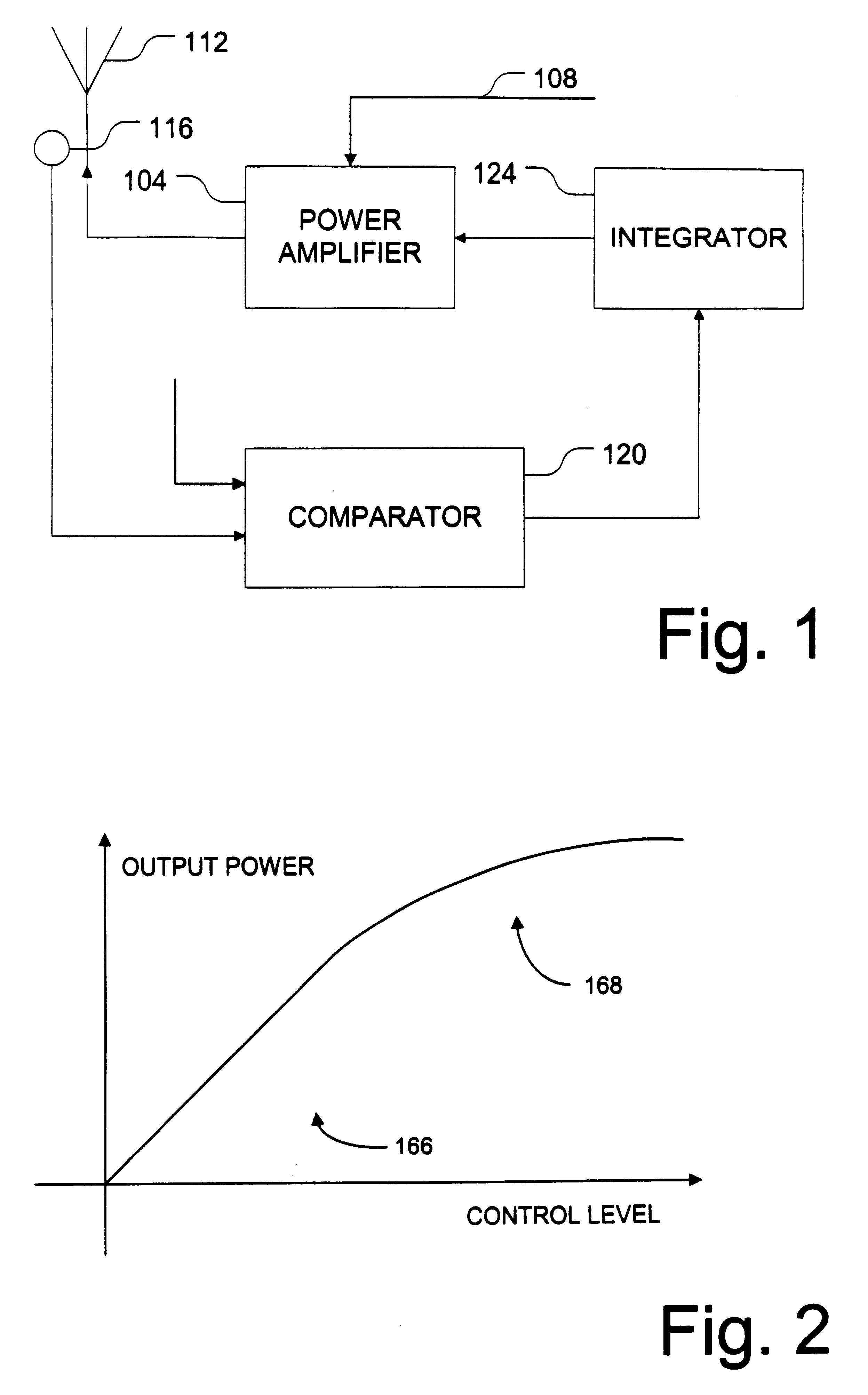
One drawback of contemporary closed-loop systems is that the power amplifier typically has a non-linear transfer function.
This can result in less-than-desirable response characteristics of the feedback loop.
For example, if the loop is operating in a region where there is too little gain, loop response may be slower than desired.
If on the other hand, the loop is operating in a region where there is too much gain, the system may go into oscillation.
In some applications, the problem is more prevalent because the power amplifier tends to primarily operate in the non-linear region.
One disadvantage of such a closed-loop system is that power amplifier 104 typically exhibits non-linear characteristics.

Method used


Image

  • Distortion control feedback loop utilizing a non-linear transfer function generator to compensate for non-linearities in a transmitter circuit
  • Distortion control feedback loop utilizing a non-linear transfer function generator to compensate for non-linearities in a transmitter circuit
  • Distortion control feedback loop utilizing a non-linear transfer function generator to compensate for non-linearities in a transmitter circuit

Examples


Embodiment Construction

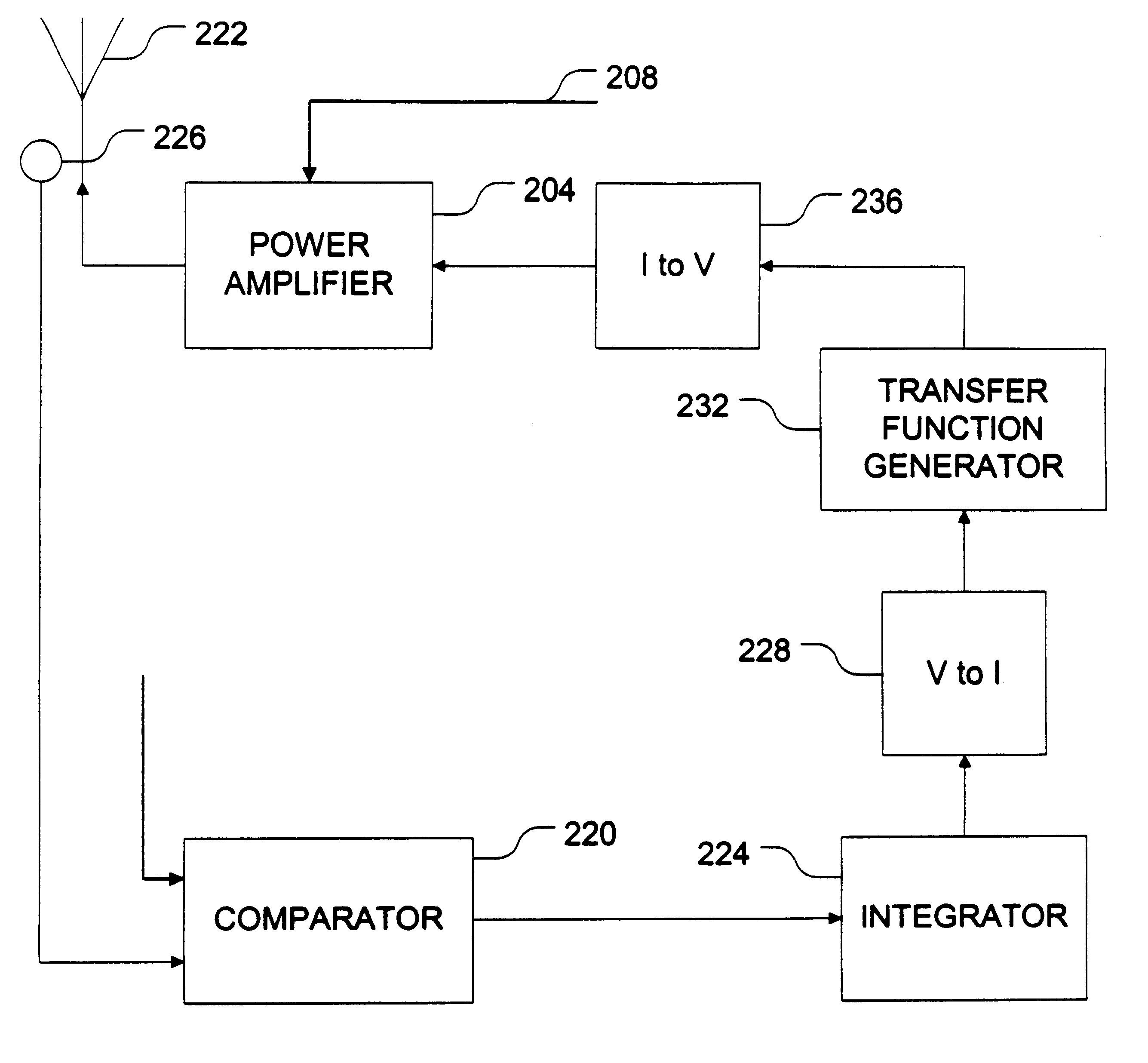
FIG. 3 is a block diagram illustrating an application of the invention in an example environment such as that illustrated in FIG. 2. Referring now to FIG. 3, a transfer function generator 232 is implemented as part of a feedback loop in a closed loop system. Specifically, in the embodiment illustrated in FIG. 3, transfer function generator is provided in the feedback loop between a comparator 220 and a power amplifier 204. Transfer function generator 232 is implemented as having a non-linear transfer function such that its response in the system compensates for other non-linearities in the system. These other non-linearities may be those associated with power amplifier 204, as well as non-linearities that may be associated with other components in the system.

In a preferred embodiment, transfer function generator 232 operates on current rather than voltage. As such, in the illustrated embodiment, converters 228, 236 are provided to convert the voltage levels from the comparator into ...


PUM


Abstract

A transfer function generator provides the ability to provide a non-linear response in a feedback loop to compensate for non-linearities introduced elsewhere in the system. The transfer function generator includes a non-linear function generator configured to provide an output current that is a non-linear function of an input signal representing an error to be corrected. The transfer function generator can also include a linear function generator configure to provide a linear output current as a function of an input current representing the error corrected. Tuning devices can be provided to adjust the turn-on level of the non-linear function generator and the output level of the linear function generator to allow the transfer function generator flexibility in implementation.

Description

1. Field of the InventionThe present invention relates generally to function generators, and more particularly to a flexible transfer function generator.2. Related ArtPower amplifiers are commonly used in a number of contemporary devices, including, for example, wireless communication devices such as handsets and basestations. In such devices, the power amplifier amplifies the modulated signal to a desired level such that the radiated power from the device's antenna is of sufficient strength to fall within the dynamic range of the intended receiver.In many applications, closed loop systems are used to control radiated power to within a relatively narrow range. Closed loop systems typically accomplish this goal through the use of a feedback loop. Such feedback loops can include, for example, a power sensor at or near the antenna to detect the actual transmitted power level. The detected power level can be compared with a desired power level to determine a difference between actual an...

Claims


Application Information

Patent Timeline
Patent Type & Authority Patents(United States)
IPC IPC(8): H03F1/32H04B1/04
CPCH03F1/3276H04B2001/0433H03F1/34H03F3/24
Inventor CIPRIANI, STEFANOCARPINETO, LORENZOTAKESHIAN, ANTHONY A.
Owner SKYWORKS SOLUTIONS INC
Learn More