
LED light fixture assembly

a technology of led light fixtures and assembly parts, which is applied in the direction of lighting and heating apparatuses, light source combinations, and with built-in power, can solve the problems of short service life, high power consumption, and the use of rare earth and other toxic phosphors to generate light, and achieve the effect of reducing energy consumption and reducing light level

Inactive Publication Date: 2017-09-12
SHEW LARRY N
View PDF5 Cites 7 Cited by
  • Summary
  • Abstract
  • Description
  • Claims
  • Application Information

AI Technical Summary

Benefits of technology

The present invention is a new LED light fixture / troffer that offers energy efficiency and environmentalfriendliness as a replacement for traditional fluorescent light tubes. It simplifies the LED fixture by eliminating socket holders at both ends and incorporating a power supply module with an LED light source that operates with only one end cap. The single end cap with two prongs eliminates the need for an AC to DC converter, reducing manufacturing costs. The invention also provides a modular design for easy addition and replacement of functions, as well as a night lighting system that adjusts brightness based on ambient light levels and a remote control sensor for programmable functions.

Problems solved by technology

The traditional fluorescent light tube troffer / fixture containing fluorescent light tubes and an electronic ballast have common drawbacks of high power consumption, short service life, and a somewhat fragile structure.
Another drawback is their use of rare-earth and other toxic phosphors needed to generate light.
This presents a problem when the tubes which have ceased to function require disposal.
The phosphors within a fluorescent light tube may present a hazardous waste situation which must be dealt with.
As such, the use of LED replacement light tubes within a new troffer / fixture would be one way of incorporating LEDs into new troffer / fixture, but it may be costly.
One reason the LED replacement tubes cost more is the additional circuitry.
For example, an AC to DC converter is typically incorporated within the tube increasing the cost of the LED replacement tube.
Using known LED replacement tubes within a new or used troffer will also require conductive sockets at both ends of the troffer resulting in additional wiring and labor costs.
Another concern with the traditional fluorescent tube troffer is the complexity of its assembly.
The fluorescent tube troffer requires an electronic ballast to power the fluorescent tubes and extensive wiring is required to connect the electronic ballast to the socket holders at both ends of the troffer resulting in a relatively higher overall cost.

Method used


Image

  • LED light fixture assembly
  • LED light fixture assembly
  • LED light fixture assembly

Examples


first embodiment

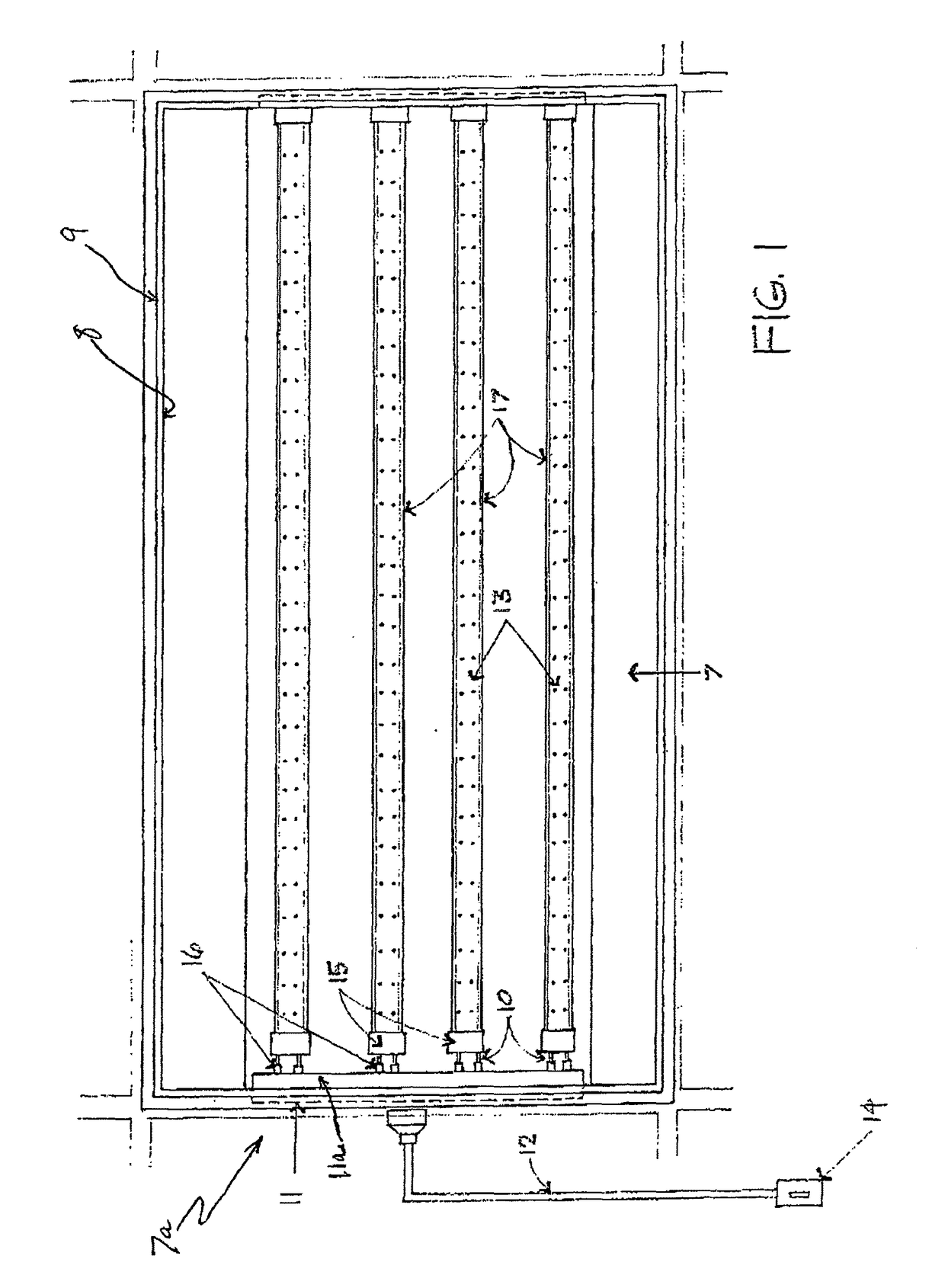
[0042]an LED lighting assembly in accordance with the present invention is illustrated in FIG. 1. A troffer / fixture 7 may contain a housing 8 and translucent or transparent cover 9, and is normally installed within an office or industrial setting, or within a suspended ceiling for example. A power supply module 11 is slidably and releasably fixed within an end section 7a of the troffer 7, for providing a source of direct current or DC power to associated LED assemblies such as strips or tubes. An AC or alternating current power source 12 electronically communicates with the module 11, thereby providing AC power for conversion into DC power within module 11. The DC power electronically communicates with an LED light source 17 by and through a singular conductive end cap on the LED light source 17. In accordance with the present invention, the power supply module 11 contains all internal circuitry necessary to provide DC power to the LED light assemblies 17 as described below, and may...

embodiment 110

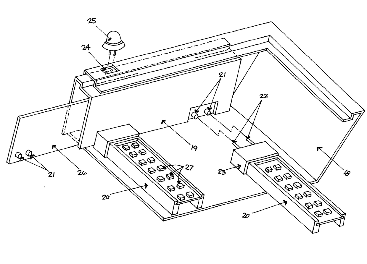
[0055]FIG. 12 illustrates a perspective view of the rear panel of an embodiment 110, similar to the one shown in FIG. 11. A power supply module 105 contains an elongated vent 106 to vent heat generated by the circuitry within the associated housing 110a. Reducing the heat keeps the temperature around the circuitry relatively lower, with a resultant increase in the longevity and efficiency of the circuitry. A connector or plug 107 located at the bottom of the power supply module housing 110a connects an AC power source 108 to the assembly 110. If desired, a switch 102 may cooperate with AC power source 108 for selectively actuating power to the assembly 110. FIG. 12 also illustrates a photocell switch 109, mounted on the rear panel 105a of the power supply module 105, and in a known manner, selectively actuates power to a limited number of LEDs as a night light in the absence or attenuation of ambient light. A motion sensor (not shown) may also be mounted on the top side of the power...


PUM


Abstract

A light assembly contains a housing. One or more LED light units are contained within the housing, wherein each of the LED light units may contain only one corresponding conductive end cap. A pair of conductors extending from each of the corresponding conductive end caps are mated with a corresponding socket contained within a DC power supply module contained within the housing.

Description

[0001]This application is a continuation of co-pending U.S. application Ser. No. 13 / 802,187 having a filing date of Mar. 13, 2013, and claims the benefit thereof. This application is herein incorporated by reference in its entirety.TECHNICAL FIELD[0002]The present invention relates to light assemblies containing solid state lighting, and more particularly, to light assemblies incorporating a modular power supply, a light emitting diode (LED) light source within the housing of a new troffer / fixture. A light assembly, in accordance with the present invention, contains a modular power supply containing an AC to DC converter, and one or more socket holders mounted onto a circuit board of the power supply module as an exemplary means to receive a singular end cap of associated DC-operated LED light tubes. In further accordance with the present invention, a circuit board contains a modular design system containing modular components that facilitates easy removal and replacement of circuit...

Claims


Application Information

Patent Timeline
Patent Type & Authority Patents(United States)
IPC IPC(8): F21K99/00F21S4/00F21S8/02F21V23/02F21Y103/00
CPCF21K9/17F21S4/008F21V23/023F21S8/026F21Y2103/003F21S9/022F21V23/0471F21Y2113/00F21Y2115/10F21K9/272F21Y2105/16F21Y2113/20F21S4/28F21K9/27
Inventor SHEW, LARRY N.
Owner SHEW LARRY N
Learn More