
Low-carbon steels of superior mechanical and corrosion properties and process of making thereof

Inactive Publication Date: 2001-08-14
CMC STEEL FABTORS
View PDF14 Cites 62 Cited by
  • Summary
  • Abstract
  • Description
  • Claims
  • Application Information

AI Technical Summary

Benefits of technology

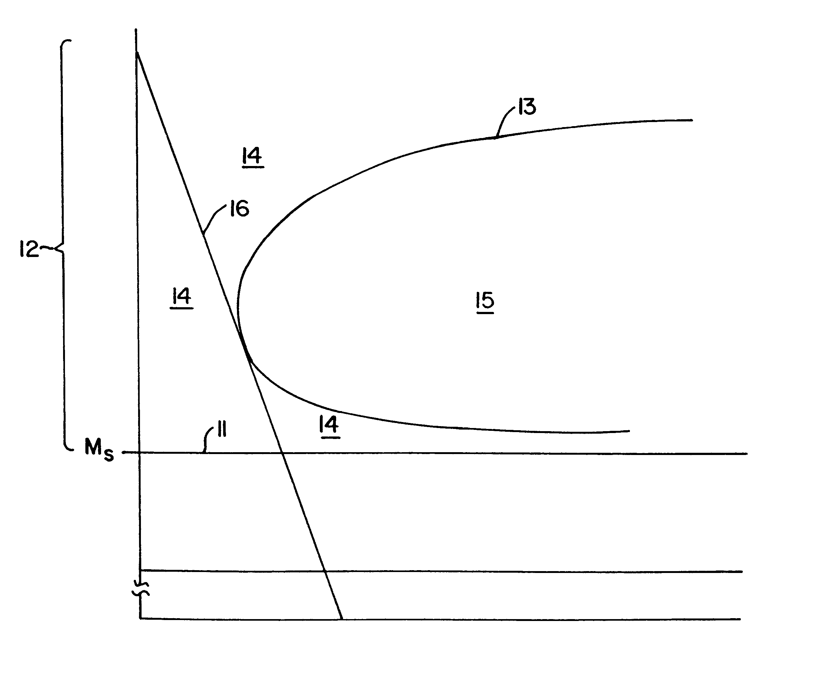
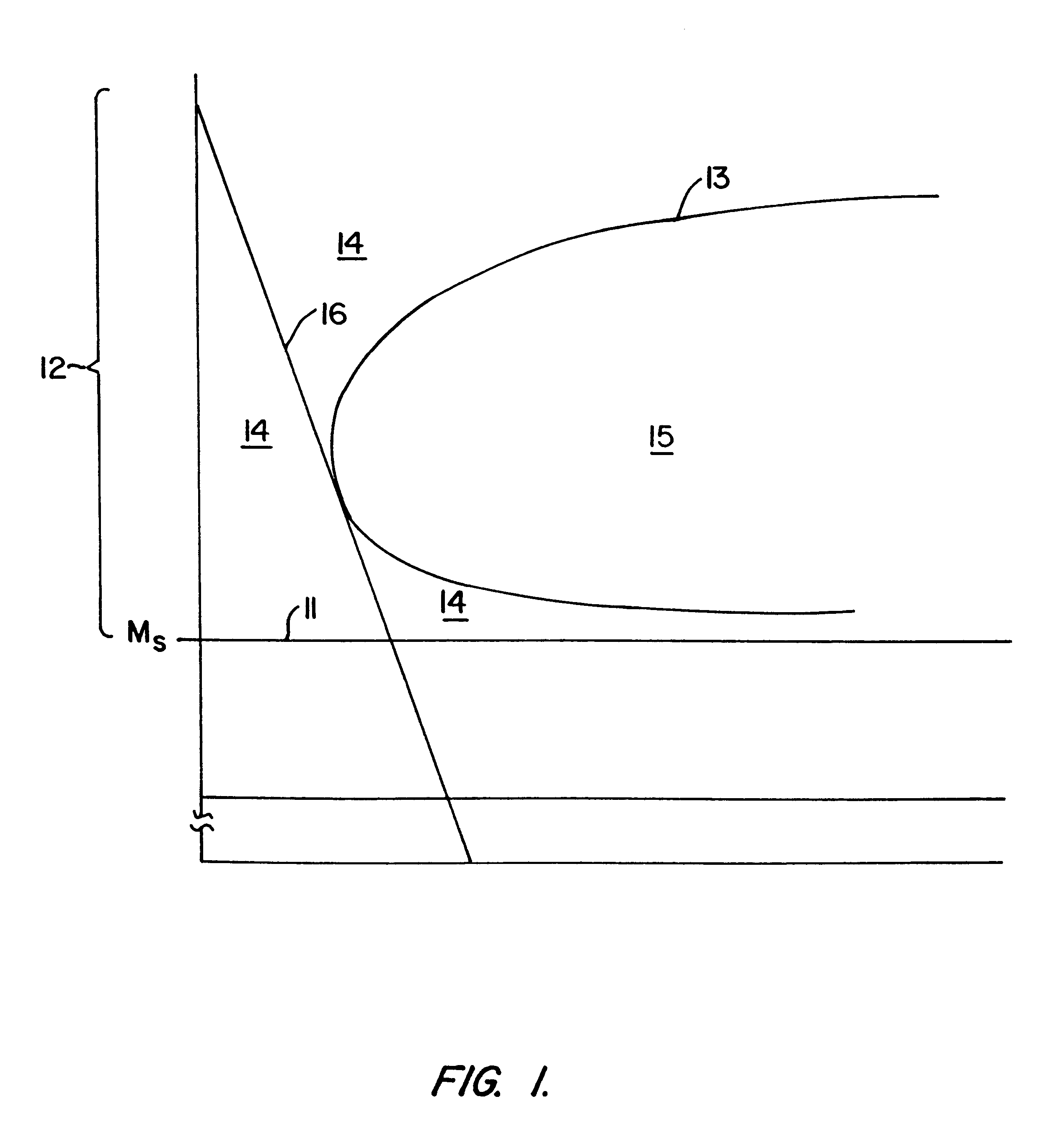
It has now been discovered that corrosion in a dislocated lath structure can be reduced by eliminating the presence of precipitates such as carbides, nitrides, and carbonitrides from the structure, including those that are produced by autotempering and also including transformation products such as bainite and pearlite containing carbides, nitrides or carbonitrides of different morphologies depending on composition, cooling rate, and other parameters of the alloying process. It has been discovered that the interfaces between the small crystals of these precipitates and the martensite phase through which the precipitates are dispersed promote corrosion by acting as galvanic cells, and that pitting of the steel begins at these interfaces. Accordingly, the present invention resides in part in an alloy steel with a dislocated lath microstructure that does not contain carbides, nitrides or carbonitrides, as well as a method for forming an alloy steel of this microstructure. The invention also resides in the discovery that this type of microstructure can be achieved by limiting the choice and the amounts of the alloying elements such that the martensite start temperature M.sub.s is 350.degree. C. or greater. Still further, the invention resides in the discovery that while autotempering and other means of carbide, nitride or carbonitride precipitation in a dislocated lath structure can be avoided by a rapid cooling rate, certain alloy compositions will produce a dislocated lath structure free of autotempered products and precipitates in general simply by air cooling. These and other objects, features, and advantages of the invention will be better understood by the description that follows.

Problems solved by technology

Alloys intended for use in certain environments require higher strength and toughness, and in general a combination of properties that are often in conflict, since certain alloying elements that contribute to one property may detract from another.

Method used


Image

  • Low-carbon steels of superior mechanical and corrosion properties and process of making thereof
  • Low-carbon steels of superior mechanical and corrosion properties and process of making thereof
  • Low-carbon steels of superior mechanical and corrosion properties and process of making thereof

Examples


Embodiment Construction

Autotempering of an alloy composition occurs when a phase that is under stress due to supersaturation with an alloying element is relieved of its stress by precipitating the excess amount of the alloying element as a compound with another element of the alloy composition in such a manner that the resulting compound resides in isolated regions dispersed throughout the phase while the remainder of the phase reverts to a saturated condition. Autotempering will thus cause excess carbon to precipitate as iron carbide (Fe.sub.3 C). If chromium is present as an additional alloying element, some of the excess carbon may also precipitate as trichromium dicarbide (Cr.sub.3 C.sub.2), and similar carbides may precipitate with other alloying elements. Autotempering will also cause excess nitrogen to precipitate as either nitrides or carbonitrides. All of these precipitates are collectively referred to herein as "autotempering (or autotempered) products" and it is the avoidance of these products ...


PUM

PropertyMeasurementUnit
start temperature Msaaaaaaaaaa
temperatureaaaaaaaaaa

Abstract

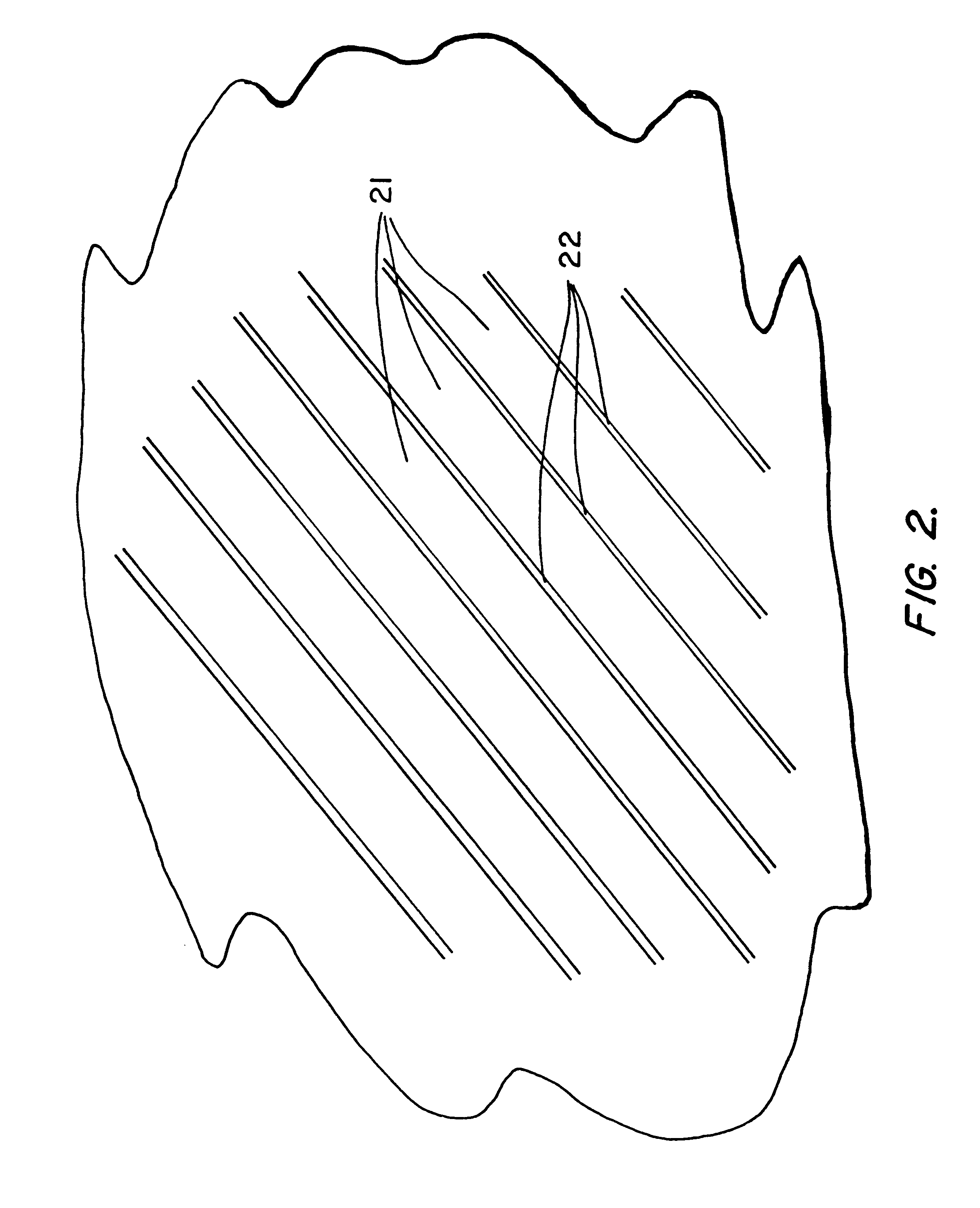
Alloy steels that combine high strength and toughness with high corrosion resistance are achieved by a dislocated lath microstructure, in which dislocated martensite laths that are substantially free of twinning alternate with thin films of retained austenite, with an absence of autotempered carbides, nitrides and carbonitrides in both the dislocated martensite laths and the retained austenite films. This microstructure is achieved by selecting an alloy composition whose martensite start temperature is 350° C. or greater, and by selecting a cooling regime from the austenite phase through the martensite transition region that avoids regions in which autotempering occurs.

Description

1. Field of the InventionThis invention resides in the field of steel alloys, particularly those of high strength, toughness, corrosion resistance, and cold formability, and also in the technology of the processing of steel alloys to form microstructures that provide the steel with particular physical and chemical properties.2. Description of the Prior ArtSteel alloys of high strength and toughness and cold formability whose microstructures are composites of martensite and austenite phases are disclosed in the following United States patents (all assigned to The Regents of the University of California), each of which is incorporated herein by reference in its entirety:U.S. Pat. No. 4,170;497 (Gareth Thomas and Bangaru V. N. Rao), issued Oct. 9, 1979 on an application filed Aug. 24, 1977U.S. Pat. No. 4,170,499 (Gareth Thomas and Bangaru V. N. Rao), issued Oct. 9, 1979 on an application filed Sep. 14, 1978 as a continuation-in-part of the above application filed on Aug. 24, 1977U.S. P...

Claims


Application Information

Patent Timeline
Patent Type & Authority Patents(United States)
IPC IPC(8): C22C38/18C22C38/34C21D1/18C21D1/22C22C38/00C21D6/00C21D6/02
CPCC21D1/18C21D1/25C21D7/02C22C38/34C22C38/18C21D2211/008C21D2211/001C21D6/002C21D6/008
Inventor THOMAS, GARETH
Owner CMC STEEL FABTORS
Learn More