
Light intensity measurement system

a measurement system and light intensity technology, applied in the field of light intensity measurement system, can solve problems such as reflection back into, and achieve the effect of improving measurement accuracy and greater flexibility in the adjustment of the illumination system

Inactive Publication Date: 2001-07-03
CARL ZEISS SMT GMBH
View PDF15 Cites 31 Cited by
  • Summary
  • Abstract
  • Description
  • Claims
  • Application Information

AI Technical Summary

Benefits of technology

The invention has as its object the provision of such a system with improved measurement accuracy and with greater flexibility of adjustment of the illumination system.

Problems solved by technology

Problems of measurement accuracy arise with increasing requirements for the accuracy of the whole exposure system and process, and with increasing variability of the whole system, particularly at the exit of the glass rod used in the system, with the variable adjustment of a reticle masking diaphragm whose diaphragm lamellae give rise to considerable reflections back into the glass rod.

Method used


Image

  • Light intensity measurement system
  • Light intensity measurement system

Examples


Embodiment Construction

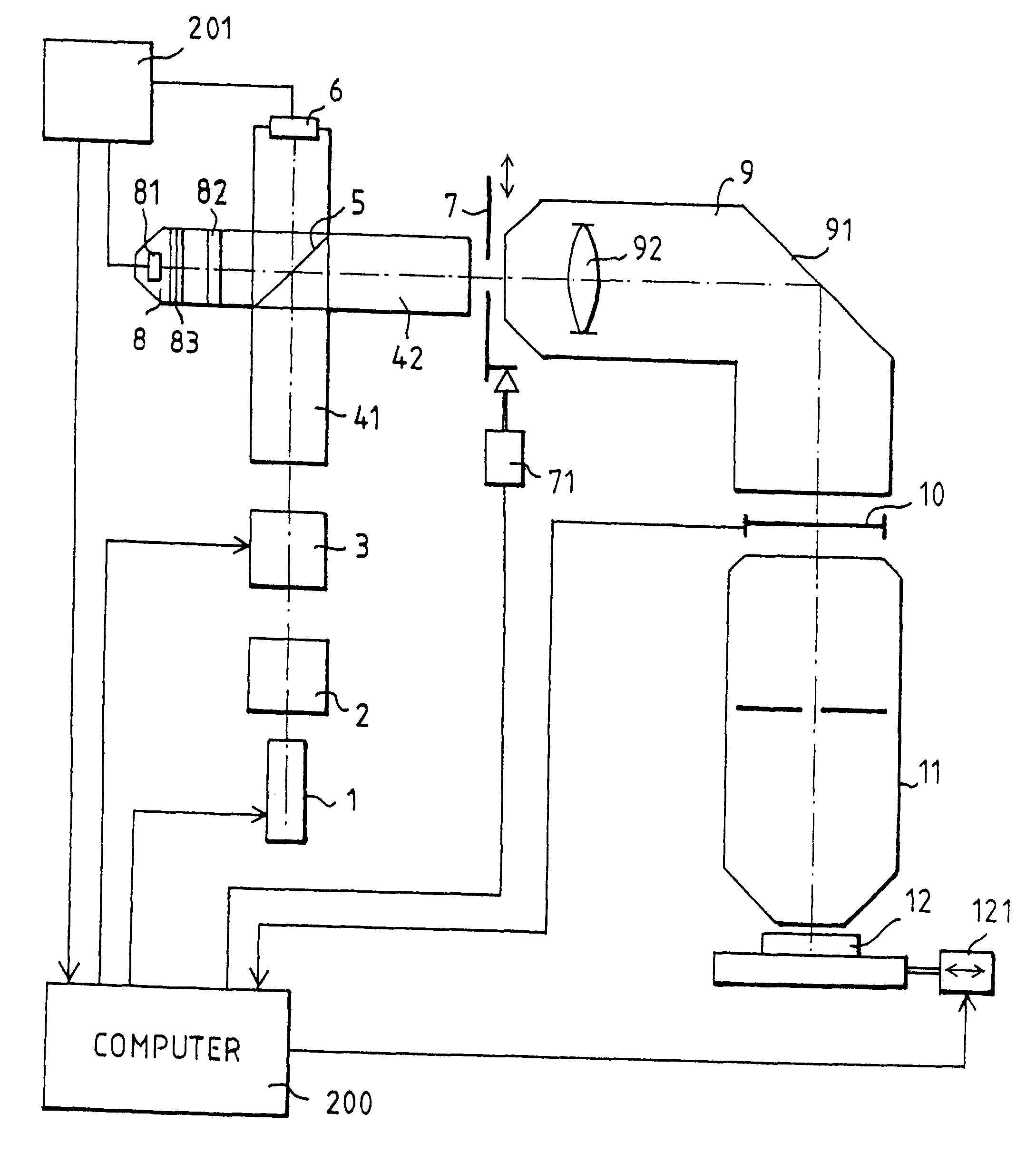
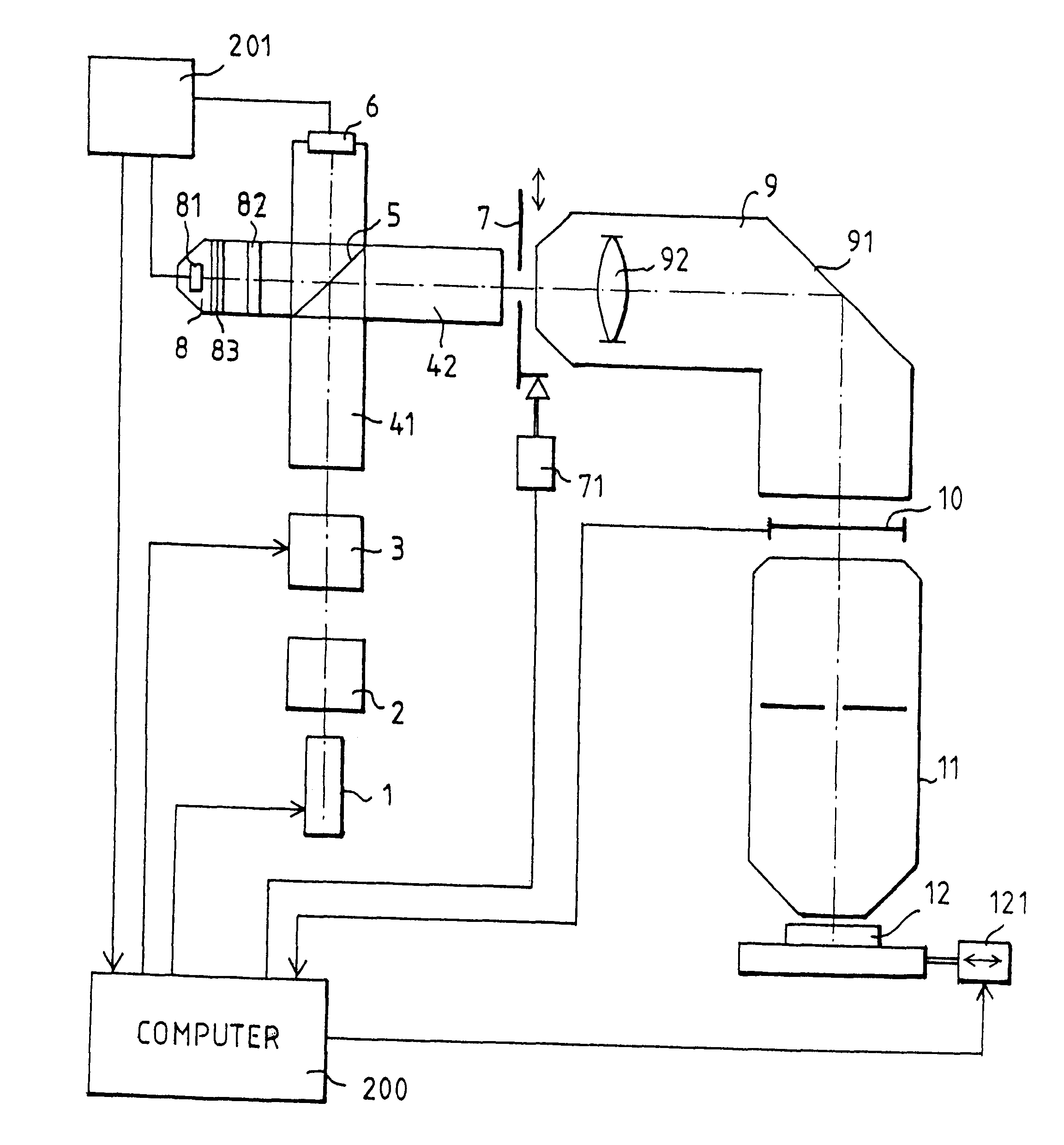
The microlithography projection illumination system shown in FIG. 1 has an excimer laser 1 as the deep ultraviolet (DUV) light source. A mirror arrangement 2 serves for coherence reduction and beam shaping. The zoom axicon objective 3 makes possible low-loss setting of classical and ring aperture illumination, with different degrees of coherence. A glass rod with two partial sections 41, 42 and a deflecting mirror 5 (provided here for reasons of the geometry of the whole apparatus) serves for homogenization of the illumination. Adjoining the glass rod is an adjustable reticle masking diaphragm 7 with an adjustment drive 71. The reticle marking (REMA) objective 9 gives a sharp-edged image of the opening of the reticle masking diaphragm 7 on the reticle 10, so that precisely that region of the mask that is to be transferred to the wafer 12 is illuminated. The projection objective 11 forms on the wafer 12 a reduced image of the mask on the reticle 10.

A deflecting mirror 91 is also prov...


PUM

PropertyMeasurementUnit
reflectivityaaaaaaaaaa
light intensityaaaaaaaaaa
flexibilityaaaaaaaaaa

Abstract

A light intensity measurement system in an illumination system of a projection illumination system for microlithography. The light intensity measurement system includes an adjustable diaphragm that reflects light back into a light-mixing glass rod. The light-mixing glass rod includes a deflecting mirror that transmits a fraction of the light intensity and an energy sensor that senses the transmitted fraction of light intensity. An adjustable diaphragm is arranged following the glass rod in the direction of light flow. The reflected light, in part, also reaches the energy sensor. A compensation detector containing a photodetector is arranged at the deflecting mirror in the main direction of the light reflected by the adjustable diaphragm.

Description

BACKGROUND OF THE INVENTION1. Field of the InventionThe invention relates to a light intensity measurement system and more particularly, to a light intensity measurement system of a projection illumination system for microlithography.2. Description of Relevant ArtSuch systems are in use in wafer steppers or scanners of the ASM-L Company, with optics of the Carl Zeiss Company, Oberkochen, Germany. International patent publication WO 97 / 31298 is a related publication. Such systems are also known from European Patent 0 500 393 B1 (FIG. 134 ).The measurement of light intensity--and thereby the energy, after integration over time--serves for the precise exposure of photoresists, and also as an input magnitude for control circuits by means of which the effects of the light flux on the optical elements (lens heating, thermal lenses) are stabilized.Problems of measurement accuracy arise with increasing requirements for the accuracy of the whole exposure system and process, and with increasi...

Claims


Application Information

Patent Timeline
Patent Type & Authority Patents(United States)
IPC IPC(8): G03F7/20G01J1/02
CPCG03F7/70058G03F7/70558G03F7/70075G03F7/70066
Inventor BADER, DIETER
Owner CARL ZEISS SMT GMBH
Learn More