Image forming apparatus provided with a plurality of image holding components
a technology of image holding components and forming apparatus, which is applied in the direction of electrographic process apparatus, instruments, optics, etc., can solve the problems of unfavorable image transfer, unstable image transfer, and unnecessary wear and tear of photosensitive drums and cleaning blades
- Summary
- Abstract
- Description
- Claims
- Application Information
AI Technical Summary
Benefits of technology
Problems solved by technology
Method used
Image
Examples
first embodiment
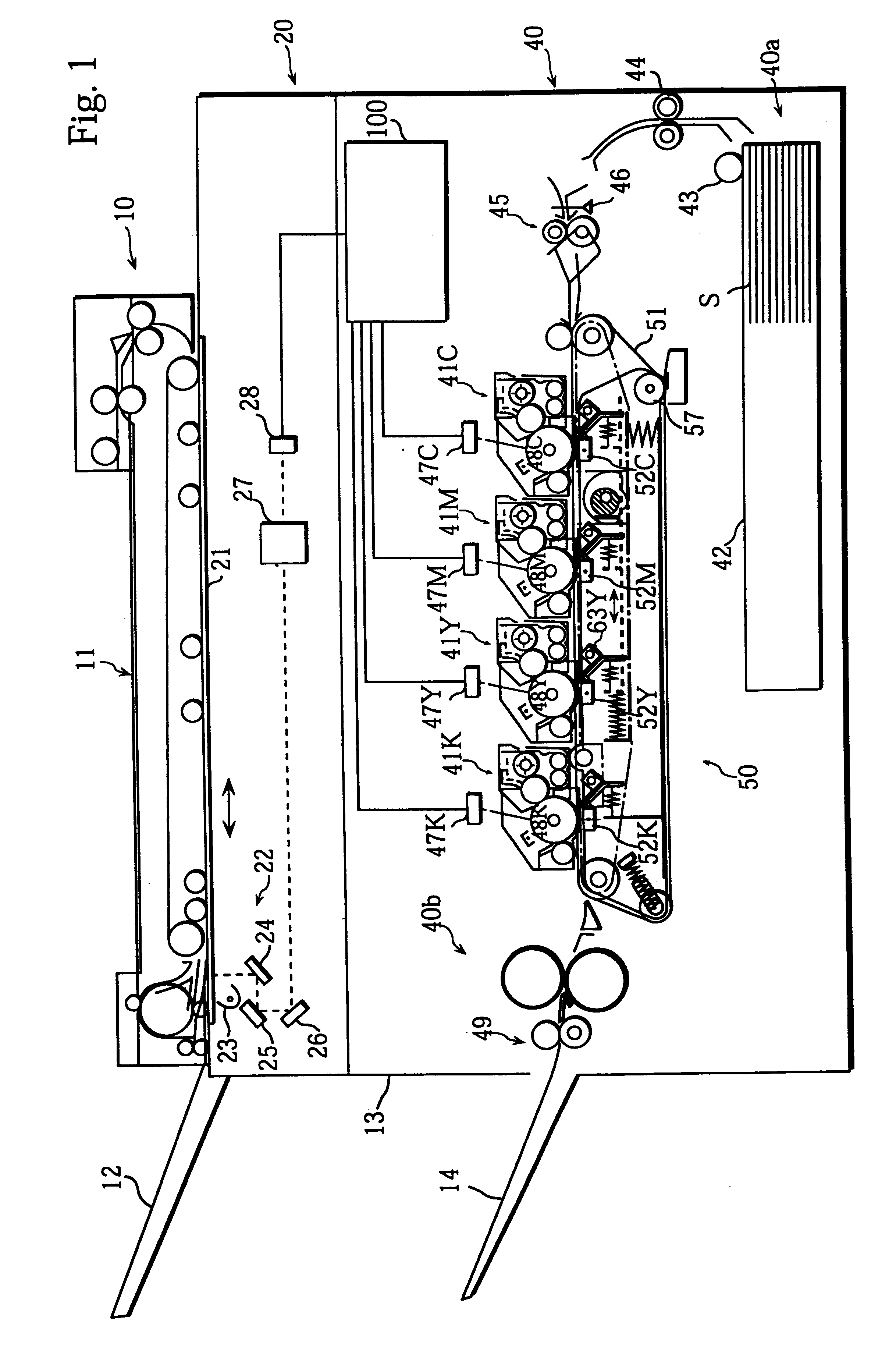
The following is a description of an embodiment of the image forming apparatus of the present invention. In this embodiment, a digital full-color copying machine is used as an example of such an image forming apparatus.
FIG. 1 is a front view of this digital full-color copying machine (simply referred to as the "copier" hereinafter).
As shown in FIG. 1, this copier is composed of an automatic document transport device 10, an image read unit 20, and a print unit 40.
The automatic document transport device 10 is a well known device which automatically transports documents set on a document feeding tray 11 to a platen glass 21 of the image read unit 20 one at a time, and which discharges each document onto a document discharge tray 12 after the document image has been read.
The image read unit 20 is provided with scanner 22 under the platen glass 21 that moves laterally, as shown by the arrow in FIG. 1. Light from the exposure lamp 23 of the scanner 22 is reflected by the document, and is ...
second embodiment
The image forming apparatus of the second embodiment is the same as the image forming apparatus of the first embodiment, except for the construction of the transfer unit as shown in the front view of FIG. 9 and certain control operations of the CPU. Therefore, the explanation of the common aspects is omitted and only the different components are explained.
The following is a description of the construction of a transfer unit 250 used in the second embodiment, with reference to FIG. 10 to FIG. 12.
FIG. 10 shows a front view of the transfer unit 250. The transfer unit 250 is composed of a main frame 253, a slide frame 254, and a shift lever 255. In FIG. 10, the main frame 253 is shown by a solid line, the slide frame 254 by a dotted line, and the shift lever 255 by a dot-dash line.
The main frame 253 is formed of a base plate 253a that has a predetermined width (parallel to the viewing direction in FIG. 10) and side plates 253b on the front side and the rear side of the base plate 253a (...
third embodiment
An image forming apparatus used in the third embodiment basically has the same construction as that in the second embodiment, although the construction of the transfer unit is different. Therefore, the common components are assigned the same numerals as in the second embodiment and no detailed explanation is given. The following description is focused on the different components.
FIG. 16 shows a front view of a transfer unit 2500 used in the third embodiment. In the second embodiment, the shift roller 290 provided for the shift lever 255 shifts up and down, so that the transport belt 251 comes into contact with and separates from the photosensitive drums 48C to 48K. In the third embodiment, on the other hand, the transport belt comes into contact with and separates from the photosensitive drums due to the transfer backups. As such, the transfer unit 2500 in the third embodiment has a construction shown in FIG. 16 where the shift lever 255, the shift roller 290, and the shift cam 275 ...
PUM
 Abstract
Description
Claims
Application Information
 - R&D
- Intellectual Property
- Life Sciences
- Materials
- Tech Scout
- Unparalleled Data Quality
- Higher Quality Content
- 60% Fewer Hallucinations
Browse by: Latest US Patents, China's latest patents, Technical Efficacy Thesaurus, Application Domain, Technology Topic, Popular Technical Reports.
© 2025 PatSnap. All rights reserved.Legal|Privacy policy|Modern Slavery Act Transparency Statement|Sitemap|About US| Contact US: help@patsnap.com


