Method for granulating and grinding molten material and device for carrying out said method

Inactive Publication Date: 2000-07-04
HOLCIM
View PDF8 Cites 13 Cited by
  • Summary
  • Abstract
  • Description
  • Claims
  • Application Information

AI Technical Summary

Benefits of technology

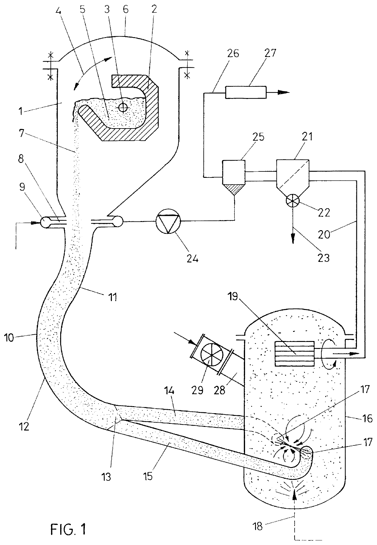
In order to further reduce offgas purification expenditures, it is advantageously proceeded in a manner that the vapour drawn off the grinding space along with the grinding material is condensed after the separation of fine stock and is recycled into the container capable of being closed in a pressure-proof manner via a compressor as compressed water, thereby enabling the remaining hydrogen sulphide to be conducted in circulation.
In order to ensure that the granulated particle stream acted upon by compressed water can be effectively introduced directly into a counter jet mill, the observance of specific parameters in regard of the flow speed of the material stream leaving the pressure-proof container is of particular importance. In accordance with the invention, it is advantageously proceeded in a manner that the flow speed of the material stream leaving the pressure-proof space via the distributor is chosen to be 10 to 30 m / s, thereby ensuring that the wear in the leading-off ducts remains controllable over a long period of time and, at the same time, precompacting of the fluidized particle stream is rendered feasible by designing the duct accordingly.
In order to obtain a particularly high grinding effect in a consecutively arranged fluidized-bed counter jet mill, the plant advantageously is dimensioned such that the nozzle outlet speed within the grinding space is chosen to be 150 to 500 m / s, wherein the grinding effect may be enhanced even further in that the pressure within the grinding space is relieved to values of below 1 bar and, in particular, 0.3 to 0.5 bar following upon the nozzle mouths. Such a pressure relief within the grinding space to values of below 1 bar may be achieved in a particularly simple manner if cold water is nozzled into the grinding space in an amount in which the dew point is not reached yet, whereby, due to cooling, a rapid condensation of the vapour outside the grinding space and hence a rapid pressure decrease under the simultaneous release of the conversion enthalpy of vapour into condensed water are feasible.
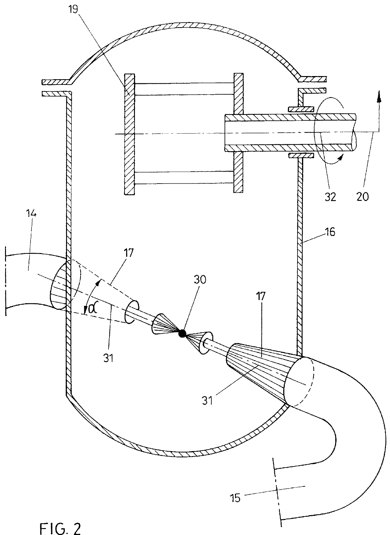
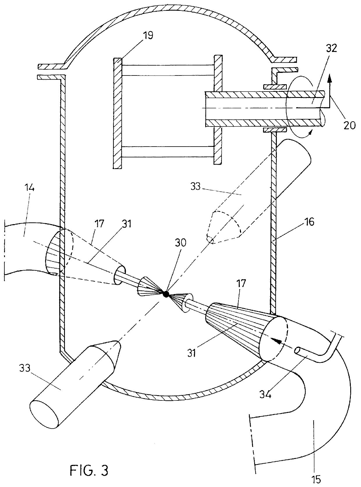
In order to ensure that the grinding space is charged correctly with a view to an efficient grinding procedure, the process advantageously is carried out in a manner that the speeds of the granulate streams and the densities of the granulate streams in different ducts following upon the distributor and leading to the nozzles are chosen so as to deviate from each other by a maximum of 8% and, prefereably, a maximum of 5%. A plurality of ducts may be connected to the distributor, each leading to different nozzles, wherein the wear of such nozzles can be substantially reduced if ceramics and, in particular, silicon carbide are chosen as materials. The inner wall of the ducts and nozzles may be additionally protected from premature wear by appropriate coatings and, in particular, ceramic coatings.
In order to safeguard the outlet speeds required for obtaining a high grinding effect and, furthermore, guarantee an acceptable service life of the nozzles, the configuration advantageously is such that the conus angle of the nozzles is chosen to be between 5.degree. and 30.degree., wherein the division of the stream into partial streams may be realized in a particularly simple manner without great structural difficulties if, as in correspondence with a preferred further development, the partial stream ducts are connected to a curvedly extending portion of the duct connected with the container capable of being closed in a pressure-proof manner. The partial stream ducts, thus, join the ducts in a region in which another change in the flow direction occurs so as to effect simple subdivision into partial streams. The small conus angle and the resulting length of the nozzle ensure that with the acceleration of the vapour speed also the particle stream is accelerated to a high degree.
As opposed to the operation of counter jet mills with compressed air, higher outlet speeds and hence an enhanced grinding effect may be obtained with the use of vapour as the propellant. In addition, further vapour and / or further grinding material may be injected via additional nozzles or by using multi-component nozzles.

Problems solved by technology

The production of such binders calls for the additional steps of drying and fine grinding the granulates, and hence two further energy-consuming processes.
By cooling in water, the low temperature heat developing can be utilized to an insufficient degree only.

Method used


Image

  • Method for granulating and grinding molten material and device for carrying out said method
  • Method for granulating and grinding molten material and device for carrying out said method
  • Method for granulating and grinding molten material and device for carrying out said method

Examples


Embodiment Construction

FIG. 1 depicts a container 1 capable of being closed in a pressure-proof manner and in which a slag ladle 2 is arranged so as to be pivotable about an axis 3 in the direction of double arrow 4. After the introduction of slag 5 into the slag ladle 2, the lid 6 of the container 1 capable of being closed in a pressure-proof manner may be closed, whereupon a slag jet 7 may be formed upon tilting of the slag ladle 2 about the axis 3. Atomization of the slag is effected by compressed water impinging on said slag jet 7, the respective annular nozzles being indicated by 8 and the annular duct for the compressed water being indicated by 9. The illustration merely is schematic, wherein the nozzle planes may be arranged radially about the slag jet 7. These nozzles might as well be arranged to be offset in the axial direction and / or inclined relative to the slag jet with conventional nozzle shapes being applicable.

Following the impingement of compressed water on the slag jet 7 via the nozzles 8...


PUM

PropertyMeasurementUnit
Pressureaaaaaaaaaa
Pressureaaaaaaaaaa
Pressureaaaaaaaaaa

Abstract

PCT No. PCT / AT98 / 00243 Sec. 371 Date Jun. 29, 1999 Sec. 102(e) Date Jun. 29, 1999 PCT Filed Oct. 14, 1998 PCT Pub. No. WO99 / 22031 PCT Pub. Date May 6, 1999In a process for granulating and comminuting molten material, the slag melt is acted upon by compressed water and discharged together with the vapour formed. The liquid slag is introduced into a granulation chamber in a free flowing jet while directing compressed water jets against the slag jet, whereupon the solidified and granulated slag is conducted through a pneumatic conveyor duct and a distributor along with the vapour formed. The partial streams leaving the distributor, via conically tapering nozzles are transferred into a grinding space exhibiting a lower pressure than the granulation space and from which the comminuted and solidified material is drawn off.

Description

1. Field of the InventionThe invention relates to a process for granulating and comminuting molten material, in which the slag melt is acted upon by compressed water and discharged together with at least a portion of the vapour formed, as well as a device for carrying out this process.2. Prior ArtMetallurgical slags of suitable chemical compositions are frequently granulated, i.e., quenched with water out of the melt flow with a view to largely preventing crystallization by rapid solidification and obtaining an amorphous glassy granule structure instead. Such granulates are valuable raw materials for the production of hydraulic binders. The production of such binders calls for the additional steps of drying and fine grinding the granulates, and hence two further energy-consuming processes.Austrian Patent No. 400 140 has already described a process for granulating and comminuting molten material and grinding material as well as a device for carrying out this process, in which the mel...

Claims


Application Information

Patent Timeline
IPC IPC(8): C21B3/00C21B3/08
CPCC21B3/08C21B2400/062C21B2400/068C21B2400/024C21B2400/076C21B2400/08Y02P10/25
Inventor EDLINGER, ALFRED
Owner HOLCIM
Why Eureka
Try Eureka