
Multi-active-region cascaded semiconductor laser

Pending Publication Date: 2022-10-27
SUZHOU EVERBRIGHT PHOTONICS CO LTD +1
View PDF2 Cites 0 Cited by
  • Summary
  • Abstract
  • Description
  • Claims
  • Application Information

AI Technical Summary

Benefits of technology

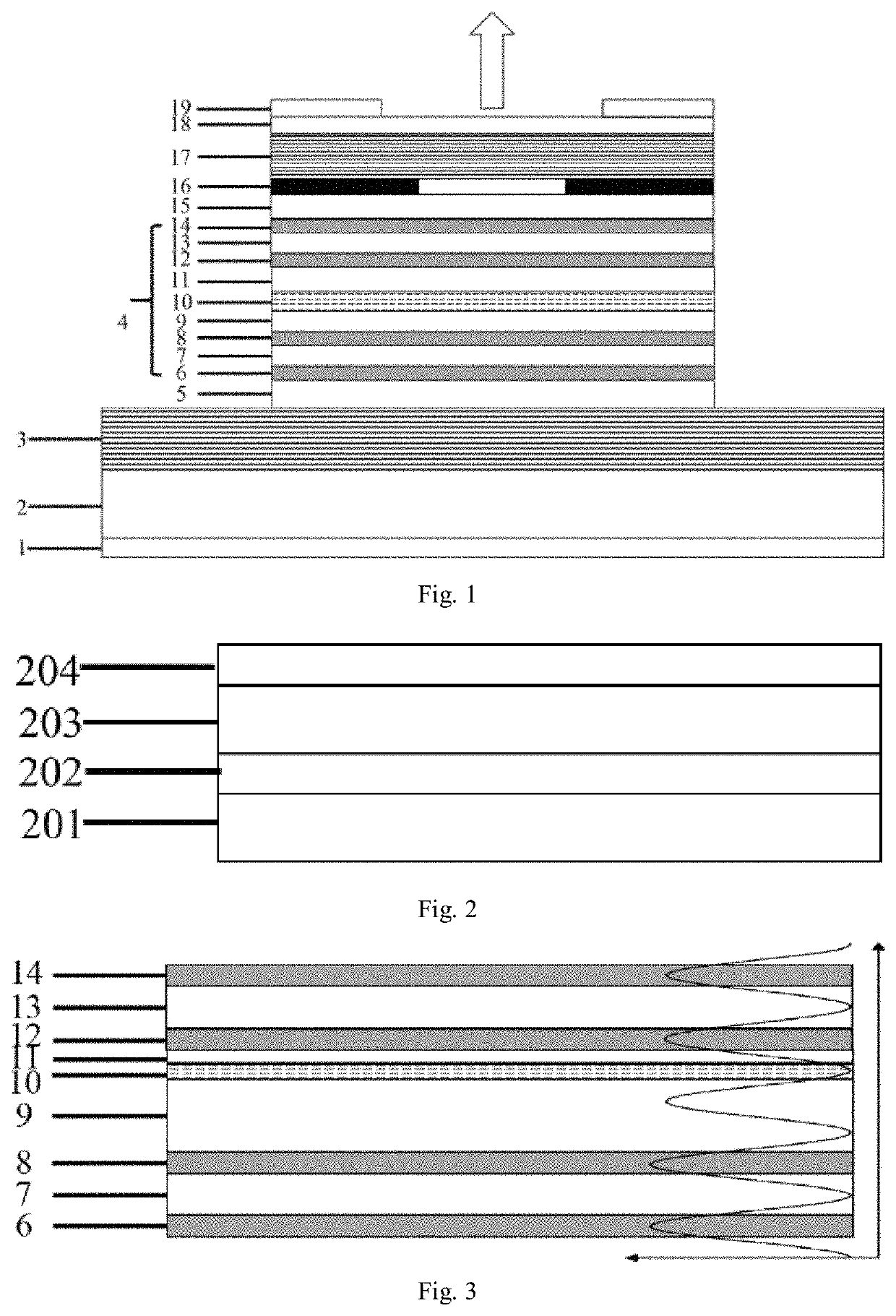
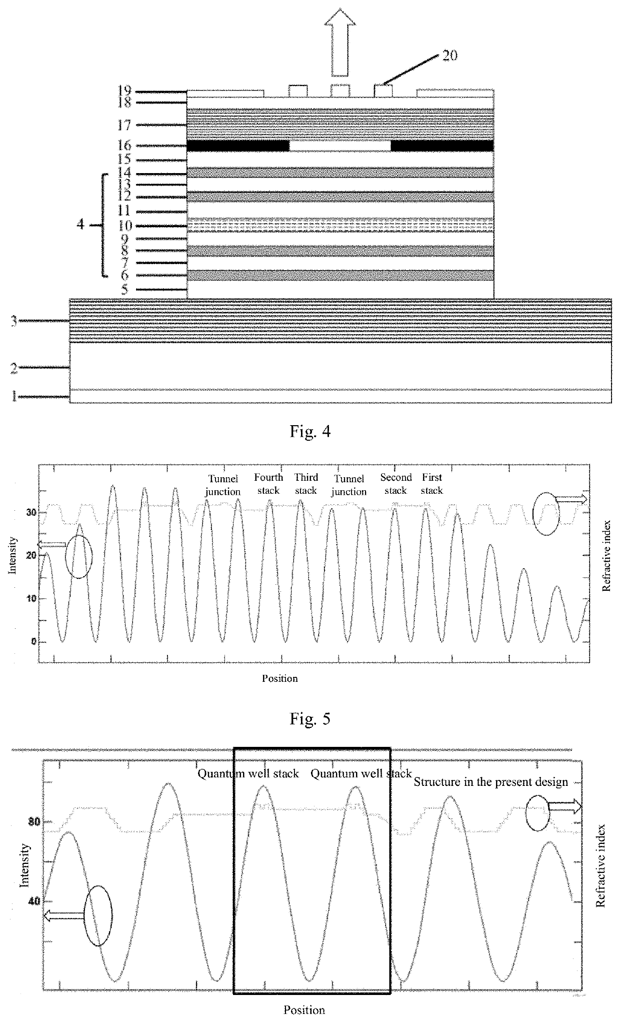
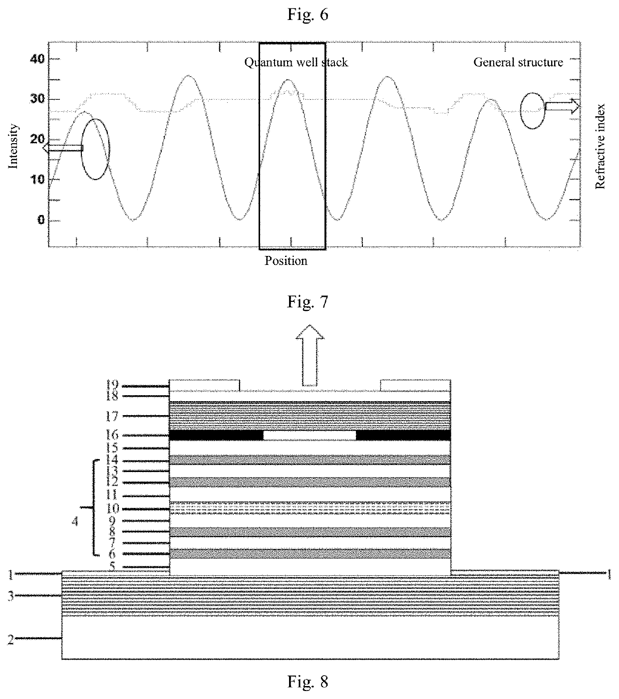
The present application provides a multi-active-region cascaded semiconductor laser with the following advantages: 1. Small number of quantum well stacks distributed in the center of each peak of the periodic optical field, increasing the intracavity gain, reducing the threshold of the device, and increasing power and efficiency of the laser. 2. Adjoining active regions connected by a barrier layer, allowing the carriers to fully compound, and then adding a tunnel junction structure, reactivating the carriers and allowing them to flow into the next active region to produce gains. This improves the internal quantum efficiency of the device and reduces the carrier density to obtain more gains. 3. The barrier layer connection does not increase the turn-on voltage, and meanwhile the epitaxial growth is simpler than that of the tunnel junction.

Problems solved by technology

However, for large 3D sensing application scenarios, such as in the field of LIDAR-based unmanned driving, the vertical-cavity surface-emitting laser of the above structure cannot satisfy requirements, and high-power and high-efficiency lasers are in need.
However, the tunnel junction is essentially a pn junction constituted by a very thin heavily-doped layer, and it is more difficult to achieve accurate heavy doping during epitaxial growth than the growth of other common epitaxial layers.
Meanwhile, as the demand for laser power and efficiency increases, and under the limitation of space and heat dissipation performance, it is increasingly difficult for the vertical-cavity surface-emitting laser with multiple active regions to satisfy the requirements for laser power and efficiency.

Method used


Image

  • Multi-active-region cascaded semiconductor laser
  • Multi-active-region cascaded semiconductor laser
  • Multi-active-region cascaded semiconductor laser

Examples


Embodiment Construction

[0036]The technical solutions of the present application will be clearly and completely described below in combination with the accompanying drawings, and obviously, the described embodiments are a part but not all of the embodiments of the present application. Based on the embodiments in the present application, all the other embodiments obtained by those skilled in the art without any creative effort shall all fall within the protection scope of the present application.

[0037]In the description of the present application, it should be noted that, the orientation or positional relationship indicated by such terms as “center”, “up”, “down”, “left”, “right”, “vertical”, “horizontal”, “inner” and “outer” is the orientation or positional relationship based on the accompanying drawings. Such terms are merely for the convenience of description of the present application and simplified description, rather than indicating or implying that the device or element referred to must be located in...


PUM


Abstract

The present application relates to the technical field of semiconductor optoelectronics, in particular to a multi-active-region cascaded semiconductor laser. The multi-active-region cascaded semiconductor laser comprises: a plurality of cascaded active regions, wherein each cascaded active region comprises a plurality of active regions; and a tunnel junction, arranged on at least one side of the cascaded active region and electrically connected with the cascaded active region; wherein in the cascaded active region, at least one group of adjacent active regions are connected through a barrier layer. In this way, more active regions are added in the periodic gain structure, which improves the internal quantum efficiency of the device and also reduces the carrier density, thereby obtaining more gains. The barrier layer connection does not have the property of introducing a new pn junction, so the layer will not increase the turn-on voltage for device operation, and meanwhile the epitaxial growth is much simpler than that of the tunnel junction.

Description

TECHNICAL FIELD[0001]The present application relates to the technical field of semiconductor optoelectronics, in particular to a multi-active-region cascaded semiconductor laser.BACKGROUND ART[0002]A vertical-cavity surface-emitting laser is a semiconductor microcavity laser, compared with the traditional edge-emitting laser, owing to the advantages of low threshold current, small size, easy fiber coupling of circular symmetric spots, high beam quality, single longitudinal mode, easy integration of surface emission, the vertical-cavity surface-emitting laser has been developed rapidly in recent years, and has been widely used in such fields as face recognition and other three-dimensional sensing, optical communication, LIDAR and unmanned driving, etc.[0003]Currently, the structure of a vertical-cavity surface-emitting laser includes: a resonator formed by an upper and a lower reflective surface, a gain region formed by stacking quantum well structures, and a current limiting layer (...

Claims


Application Information

Patent Timeline
IPC IPC(8): H01S5/183H01S5/34H01S5/028
CPCH01S5/18397H01S5/3416H01S5/028H01S5/187H01S5/426H01S5/3401H01S5/3407H01S5/18383H01S5/3095H01S5/18311H01S5/18358H01S5/18386
Inventor WANG, JUNXIAO, YAOTAN, SHAOYANGLIU, HENGLI, QUANLING
Owner SUZHOU EVERBRIGHT PHOTONICS CO LTD
Learn More