
Swimming Pool Pressure and Flow Control Pumping and Water Distribution Systems and Methods

a technology of pumping and water distribution system and swimming pool, which is applied in the direction of positive displacement liquid engine, process and machine control, instruments, etc., can solve the problems of pool/spa system that does not properly operate, pool/spa system that does not provide predictable and precise water flow to all combinations of pool/spa equipment, poor performance and efficiency of pool/spa pumping and distribution system, etc., to maximize performance and efficiency, the effect of maximizing energy efficiency

Pending Publication Date: 2022-10-27
HAYWARD IND INC
View PDF0 Cites 0 Cited by
  • Summary
  • Abstract
  • Description
  • Claims
  • Application Information

AI Technical Summary

Benefits of technology

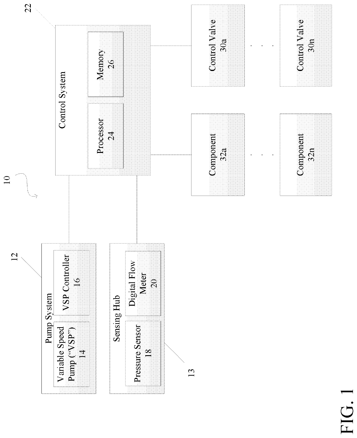
The present patent is about a system for controlling the pressure and flow of water in a swimming pool or spa. The system allows for precise control of the water flow to each swimming pool component, maximizing performance and efficiency. The control system uses a variable speed pump and an adjustable fluid circuit control valve to provide the required flow while minimizing energy consumption. The control system can also prioritize the pool system components and deactivate the component with the highest priority if the current total flow requirement exceeds the pump's capacity. Overall, the system provides a predictable and efficient water flow for swimming pools and spas.

Problems solved by technology

Typically, in the pool and spa field, current applications of variable speed pumps within the swimming pool environment do not supply predictable and precise water flow to all combinations of pool / spa equipment.
However, determining flow settings for multiple components in a single system can sometimes be unpredictable, which can result in improper flow being provided to the components and cause poor performance and efficiency of the pool / spa pumping and distribution system.
The result is a pool / spa system that does not properly operate and utilizes excessive energy.
Further, the operational configuration of current variable speed pump technology does not always achieve the intended variable speed benefit, as such pumps might not always operate at the lowest possible motor speed or conserve pump motor horsepower energy.
However, the actual result is that the associated components might underperform or not perform at all, which can result in excessive run times, system inefficiency, and increased power usage.
Additionally, in some scenarios, total GPM (gallons per minute) required by the components might exceed the maximum capacity of the pump, e.g., when multiple system component's demands exceed pump capacity.
In such situations, the total GPM flow is reduced to all components, which can further reduce performance and proper system operation, and waste pump motor energy.
However, current “non-smart” variable speed pumping technology can sometimes operate independent of system component requirements, and instead vary the flow based on a programmed setting or component control interlock.
In such systems, exact flow to each component is often unknown and unpredictable based on system variables.

Method used


Image

  • Swimming Pool Pressure and Flow Control Pumping and Water Distribution Systems and Methods
  • Swimming Pool Pressure and Flow Control Pumping and Water Distribution Systems and Methods
  • Swimming Pool Pressure and Flow Control Pumping and Water Distribution Systems and Methods

Examples


first embodiment

[0032]FIG. 4 is a schematic diagram showing a system 60 in the dynamic pressure control mode of operation. As shown in FIG. 4 the system 60 includes a variable speed pump 62, a pump controller 64, a control system 66, a pressure sensor 68, a flow meter 70, a plurality of control valves 72a-72e, and a plurality of components 74a-74e. A pool suction main pipe 75 is connected to an inlet of the variable speed pump 62, and a pool return main pipe 76 is connected to an outlet of the variable speed pump 62, such that water is drawn from a pool through the pool suction main pipe 75 into the variable speed pump 62, and discharged from the variable speed pump 62 through the pool return main pipe 76 to the control valves 72a-72e, which control the flow of water to the components 74a-74e. The pool return main pipe 76 can be a part of a plumbing subsystem that places the components 74a-74e in fluidic communication with the variable speed pump 62, and the control valves 72a-72e can be placed in ...

second embodiment

[0034]FIG. 5 is a schematic diagram showing system 80 in the programmed RPM set point control mode of operation. As shown in FIG. 5, the system 80 includes a variable speed pump 82, a pump controller 84, a control system 86, a pressure sensor 88, a flow meter 90, a plurality of control valves 92a-92e, and a plurality of components 94a-94e. A pool suction main pipe 95 is connected to an inlet of the variable speed pump 82, and a pool return main pipe 96 is connected to an outlet of the variable speed pump 82, such that water is drawn from a pool through the pool suction main pipe 95 into the variable speed pump 82, and discharged from the variable speed pump 82 through the pool return main pipe 96 to the control valves 92a-92e, which control the flow of water to the components 94a-94e. The pool return main pipe 96 can be a part of a plumbing subsystem that places the components 94a-94e in fluidic communication with the variable speed pump 82, and the control valves 92a-92e can be pla...

third embodiment

[0037]FIG. 6 is a schematic diagram showing a system 100 including a manual component pressure set-up with automatic ON / OFF component and pump control. As shown in FIG. 6, the system 100 includes a variable speed pump 102, a pump controller 104, a controller / control system 106, a pressure sensor 108, a flow meter 110, a plurality of control valves 112a-112e, a plurality of components 114a-114e, and a plurality of manual volume / pressure control devices 116a-116e (e.g., adjustable valves). A pool suction main pipe 115 is connected to an inlet of the variable speed pump 102 and a pool return main pipe 117 is connected to an outlet of the variable speed pump 102, such that water is drawn from a pool through the pool suction main pipe 115 into the variable speed pump 102, and out through the pool return main pipe 117 to the control valves 112a-112e, which control the flow of water to the manual volume / pressure control devices 116a-116e which in turn control the flow of water to the compo...


PUM


Abstract

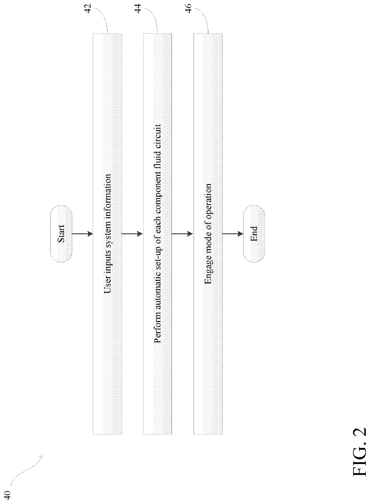
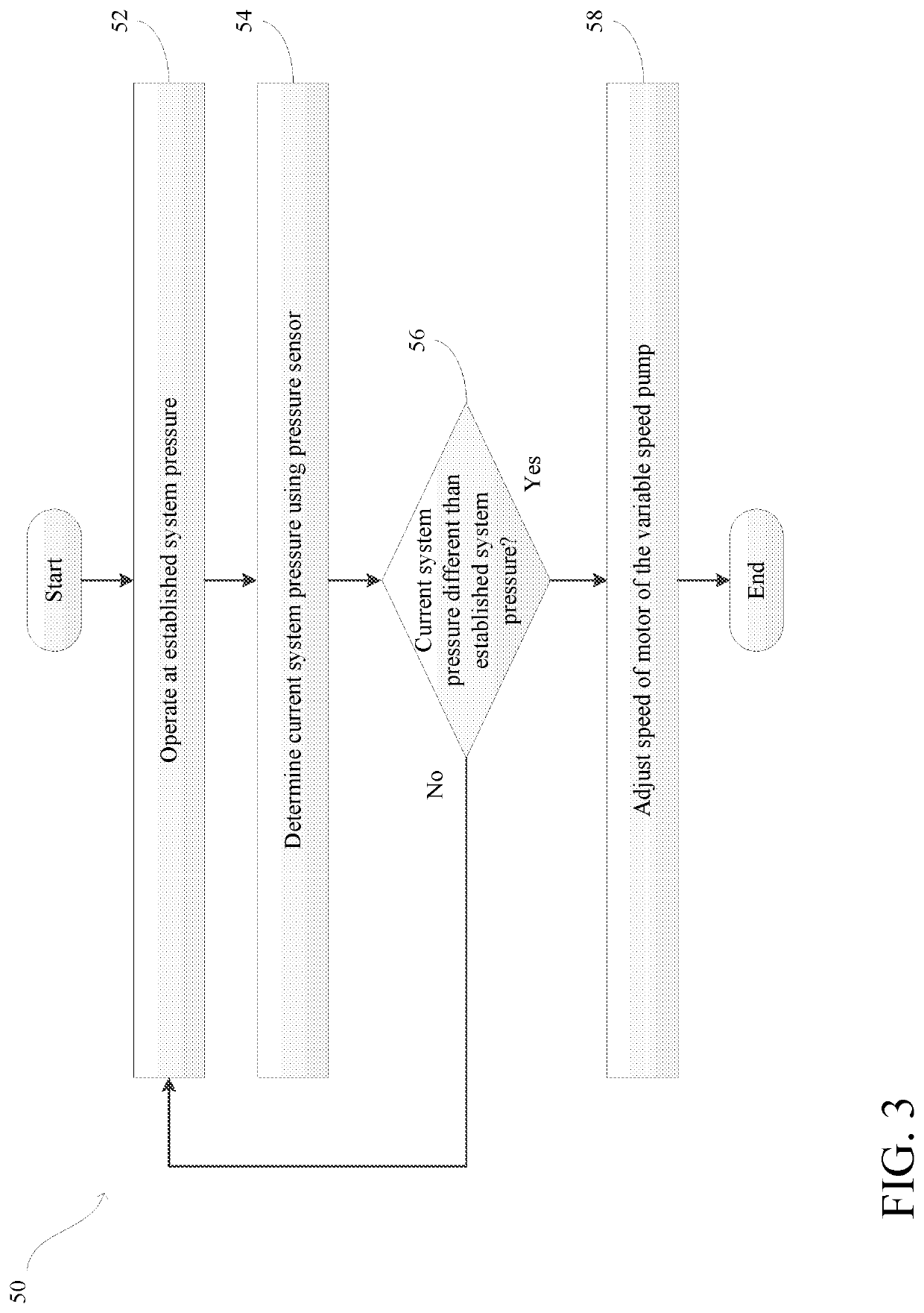
Pumping and water distribution systems for pools / spas, and methods for control thereof are provided. A system includes a pump including a variable speed motor, a controller configured to control the speed of the motor, a plurality of pool / spa components, a plumbing subsystem placing the components in fluidic communication with the pump, and a plurality of control valves switchable between an open position and a closed position. Each of the control valves is associated with one of the components, positioned in the plumbing subsystem between the associated component and the pump to control the flow of fluid to the associated component, and is configured to provide a specific flow rate of fluid to the associated component based on a set system pressure when in the open position. The controller adjusts the speed of the motor to adjust the fluid pressure within the plumbing subsystem to match the set system pressure value.

Description

CROSS-REFERENCE TO RELATED APPLICATIONS[0001]This application claims the benefit of priority to U.S. Provisional Patent Application Ser. No. 62 / 899,021, filed on Sep. 11, 2019, the entire disclosure of which is hereby incorporated by reference.TECHNICAL FIELD[0002]The present disclosure relates generally to systems and methods for pressure and flow control in pool and spa equipment. More specifically, the present disclosure relates to swimming pool pressure and flow control pumping and water distribution systems and methods.RELATED ART[0003]Typically, in the pool and spa field, current applications of variable speed pumps within the swimming pool environment do not supply predictable and precise water flow to all combinations of pool / spa equipment. Generally, in prior art systems, the desired flow to various pool / spa system components (e.g., pool / spa equipment) is established during initial system set-up by assigning a given pump RPM (revolutions per minute) operating parameter base...

Claims


Application Information

Patent Timeline
Patent Type & Authority Applications(United States)
IPC IPC(8): E04H4/12G05D7/06
CPCE04H4/12G05D7/0688F04B49/22F04B49/20F04B49/08F04B2205/09F04D15/0066F04D15/0088F05D2270/301F04B49/065
Inventor GOETTL, STEVEN JAMESCONN, DOMINICGOETTL, JOHN M.WALDEN, MARK
Owner HAYWARD IND INC
Learn More