Processing method of workpiece

a processing method and workpiece technology, applied in the direction of grinding drives, manufacturing tools, lapping machines, etc., can solve the problems of processing failures such as chipping and/or cracking processing failures are prone to occur at the outer peripheral portion of the workpiece, so as to achieve the effect of shortening the grinding tim

Pending Publication Date: 2022-10-13
DISCO CORP
View PDF1 Cites 2 Cited by
  • Summary
  • Abstract
  • Description
  • Claims
  • Application Information

AI Technical Summary

Benefits of technology

The present invention provides a processing method for a workpiece that can shorten the grinding time while suppressing the occurrence of processing failures. The method involves sequential coarse grinding and finish grinding steps using grinding stones containing abrasive grains of large and small grain sizes, respectively. By switching from coarse grinding to finish grinding before the workpiece is thinned to a predetermined thickness, the occurrence of processing failures at the outer peripheral portion of the workpiece is suppressed. The method also involves pre-removing the workpiece with the first grinding stones to increase the processing feed rate when the outer peripheral portion is ground with the second grinding stones, resulting in a faster processing time.

Problems solved by technology

As a result, processing failures such as chipping and / or cracking may occur at the outer peripheral portion of the workpiece.
When the chamfered workpiece is thinned, an outer peripheral portion of the workpiece is formed into a sharp thin shape (sharp edge shape), so that, in the final stage of the coarse grinding step, processing failures are prone to occur at the outer peripheral portion of the workpiece.
Accordingly, the grinding of the workpiece is switched from coarse grinding to finish grinding before the workpiece is thinned to such an extent that processing failures would become prone to occur at the outer peripheral portion of the workpiece.
Nonetheless, the progress of grinding of the workpiece is slow in the finish grinding compared with the coarse grinding, so that time takes to thin the workpiece.

Method used


Image

  • Processing method of workpiece
  • Processing method of workpiece
  • Processing method of workpiece

Examples


Embodiment Construction

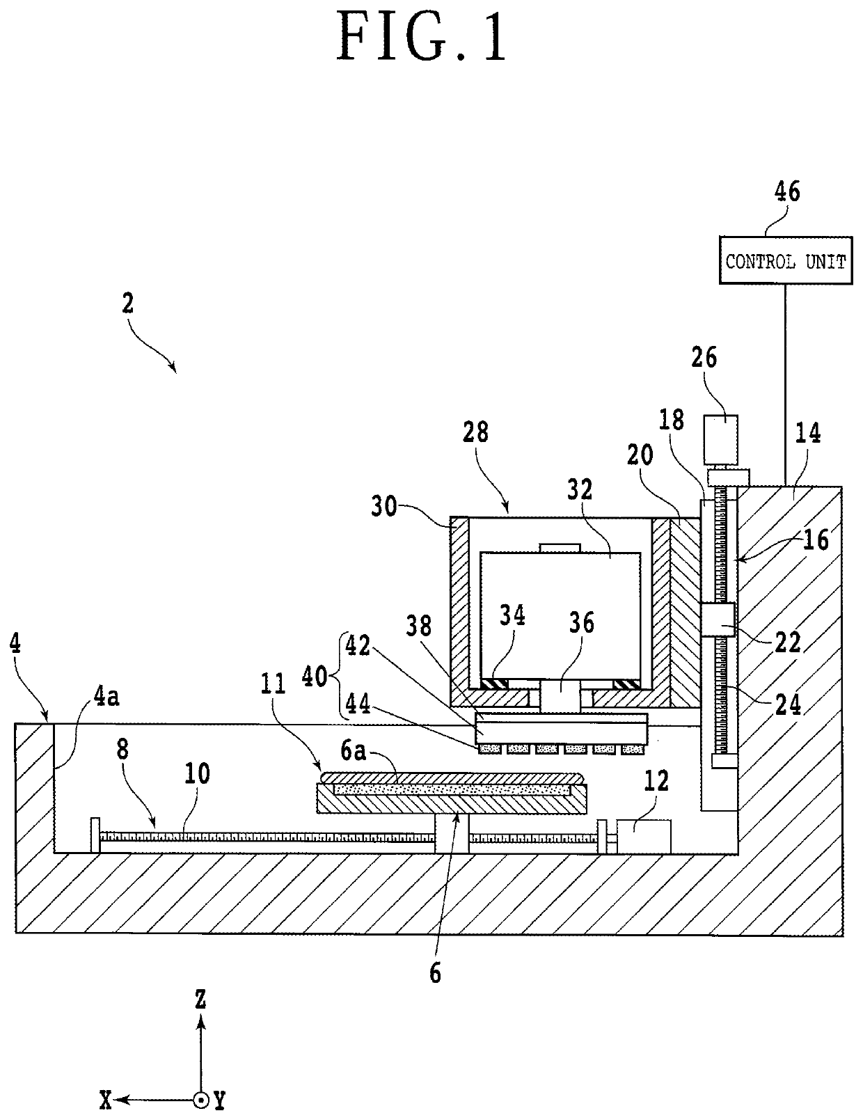
[0023]With reference to the attached drawings, an embodiment of the aspect of the present invention will be described. First, a description will be made about a configuration example of a grinding apparatus usable in a processing method of a workpiece according to the present embodiment. FIG. 1 is a partially cross-sectional side view depicting the grinding apparatus 2. It is to be noted that, in FIG. 1, an X-axis direction (first horizontal direction, front-and-rear direction) and a Y-axis direction (second horizontal direction, left-and-right direction) are perpendicular to each other. It is also to be noted that a Z-axis direction (processing feed direction, height direction, vertical direction, up-and-down direction) is perpendicular to the X-axis direction and the Y-axis direction.

[0024]The grinding apparatus 2 includes a bed 4, which supports or accommodates individual constituent elements that make up the grinding apparatus 2. On a side of an upper surface of the base 4, a re...


PUM

PropertyMeasurementUnit
widthaaaaaaaaaa
grain sizeaaaaaaaaaa

Abstract

There is provided a processing method of grinding a workpiece. The processing method includes a holding step of holding the workpiece on a side of its front surface on a chuck table, a coarse grinding step of grinding the workpiece on a side of its back surface with first grinding stones until the workpiece has a predetermined thickness, an auxiliary grinding step of grinding the workpiece on the side of its back surface with the first grinding stones such that an unground region remains at an outer peripheral portion of the workpiece, an unground region grinding step of grinding the unground region with second grinding stones having an average abrasive grain size smaller than that of the first grinding stones, and a finish grinding step of grinding the workpiece on the side of its back surface with the second grinding stones until the workpiece has a predetermined finish thickness.

Description

BACKGROUND OF THE INVENTIONField of the Invention[0001]The present invention relates to a processing method of a workpiece, which is useful in grinding workpieces, for example, wafers.Description of the Related Art[0002]In a manufacturing process of device chips, a wafer with devices formed in respective regions defined by a plurality of intersecting streets (scheduled division lines) is used. By dividing this wafer along the streets, the device chips are obtained with the devices included therein respectively. Such device chips are incorporated in various kinds of electronic equipment such as mobile phones and personal computers.[0003]In recent years, along with the downsizing of electronic equipment, there is an increasing need for thinner device chips. Before dividing a wafer, a thinning step may therefore be performed by grinding the wafer with a grinding apparatus. The grinding apparatus includes a chuck table that holds a workpiece thereon, and a grinding unit that applies gri...

Claims


Application Information

Patent Timeline
Patent Type & Authority Applications(United States)
IPC IPC(8): B24B37/34B24B7/22B24B37/27B24B7/04
CPCB24B37/345B24B7/228B24B37/27B24B7/04B24B19/00B24B27/0076B24B27/02B24B41/06B24B47/12B24B55/00H01L21/02021H01L21/02013B24B41/005B24B41/068B24B51/00B24B49/04B24B7/22H01L21/304
Inventor SUZUKI, YOSHIKAZU
Owner DISCO CORP
Why Eureka
Try Eureka