
Method for adhering noble metal to carbon steel member of nuclear power plant and method for preventing adhesion of radionuclides to carbon steel member of nuclear power plant

Pending Publication Date: 2022-07-07
HITACHI-GE NUCLEAR ENERGY LTD
View PDF3 Cites 0 Cited by
  • Summary
  • Abstract
  • Description
  • Claims
  • Application Information

AI Technical Summary

Benefits of technology

The patent text describes a method for preventing the adhesion of radionuclides to carbon steel members of a nuclear power plant. The method involves the formation of a stable nickel ferrite film on the surface of the carbon steel members. The method reduces the time required for the adhering process and also reduces the amount of iron ions released during the process. This promotes the formation of a nickel metal film and reduces the time required for the work of adhering the noble metal to carbon steel members. Ultimately, this method improves the efficiency and safety of the nuclear power plant.

Problems solved by technology

However, even if the above-mentioned corrosion prevention measures are taken, the presence of a very small amount of metal impurities in the reactor water is unavoidable.
However, the radioactive material that has not been removed is accumulated on the surface of the component members that contact the reactor water while circulating in the recirculation system or the like together with the reactor water.
As a result, radiation is radiated from the surface of the component members, which causes radiation exposure of the worker during the regular inspection work.

Method used


Image

  • Method for adhering noble metal to carbon steel member of nuclear power plant and method for preventing adhesion of radionuclides to carbon steel member of nuclear power plant
  • Method for adhering noble metal to carbon steel member of nuclear power plant and method for preventing adhesion of radionuclides to carbon steel member of nuclear power plant
  • Method for adhering noble metal to carbon steel member of nuclear power plant and method for preventing adhesion of radionuclides to carbon steel member of nuclear power plant

Examples


example 1

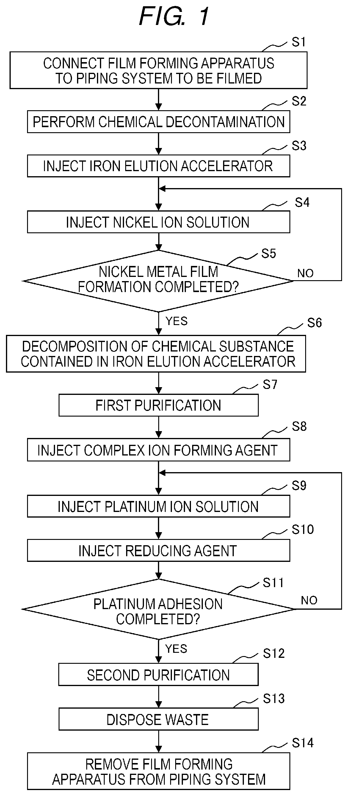
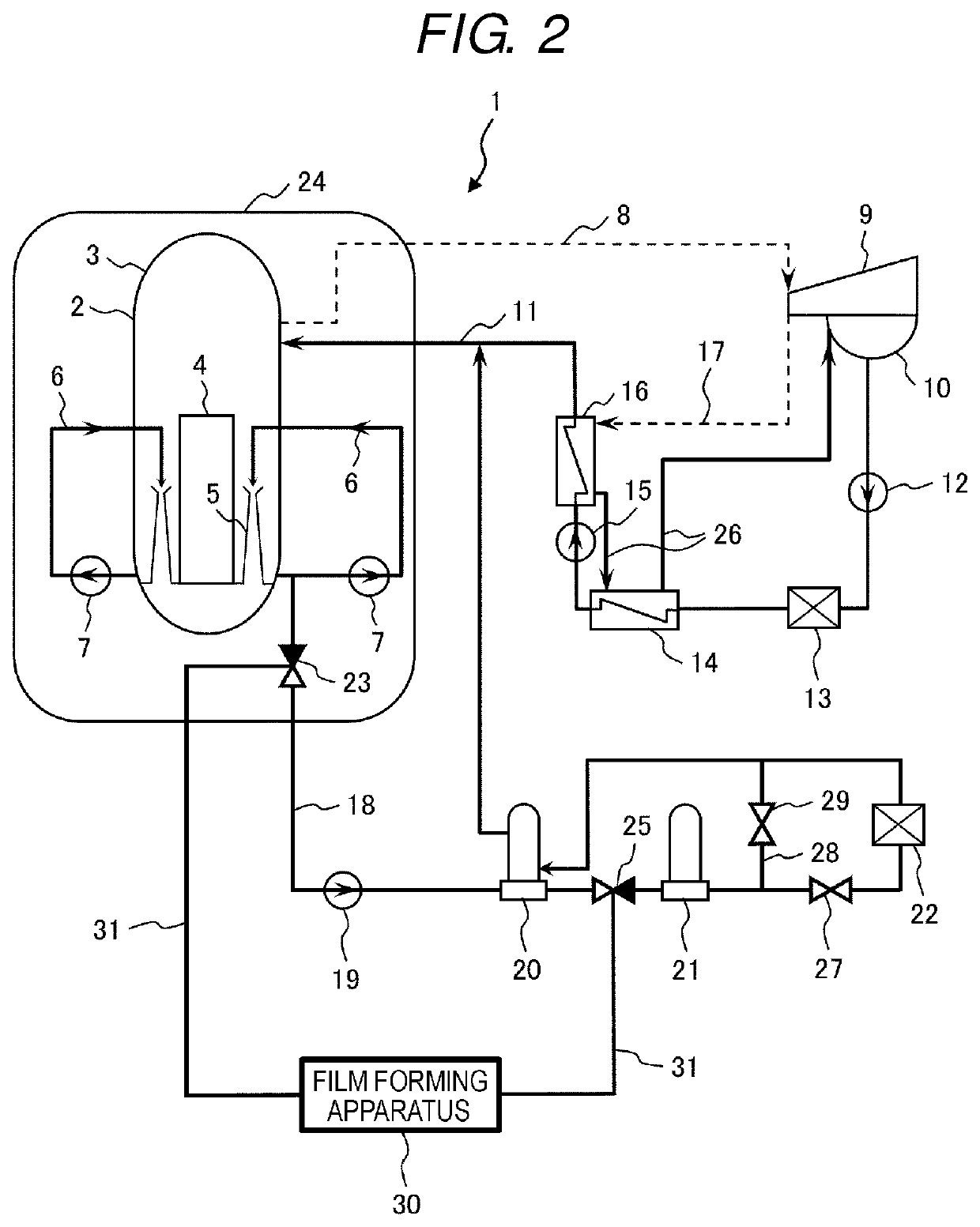
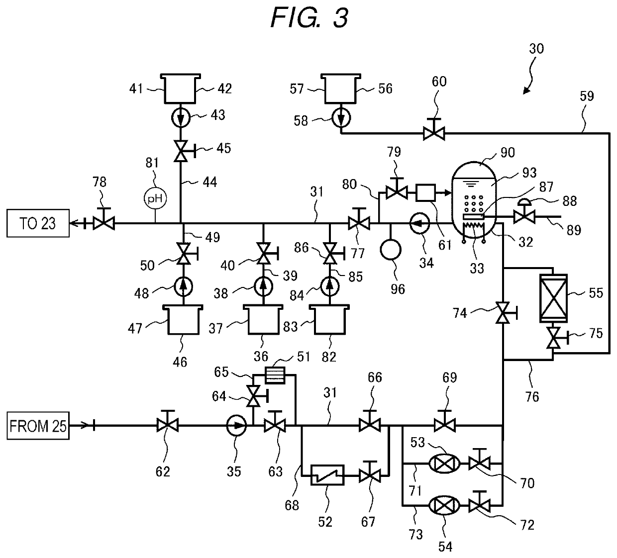
[0067]The method for adhering noble metal to a carbon steel member of a nuclear power plant of Example 1, which is a preferred embodiment of the present invention, will be described with reference to FIGS. 1, 2, and 3. The method for preventing the adhesion of radionuclides to a carbon steel member of a nuclear power plant of the example is applied to a carbon steel cleanup system pipe (carbon steel member) of a boiling-water nuclear power plant (BWR plant).

[0068]The schematic configuration of the BWR plant will be described with reference to FIG. 2. The BWR plant 1 includes a reactor 2, a turbine 9, a condenser 10, a recirculation system, a reactor cleanup system, a feedwater system, and the like. The reactor 2 is a steam generator, includes a reactor pressure vessel (hereinafter referred to as RPV) 3 including a built-in core 4, and is installed with a plurality of jet pumps 5 in an annular downcomer formed between an outer surface of a core shroud (not shown) surrounding the core...

example 2

[0147]The method for adhering noble metal to a carbon steel member of a nuclear power plant of Example 2, which is another preferred embodiment of the present invention, will be described with reference to FIGS. 8, 2, and 9. The method for adhering noble metal to a carbon steel member of a nuclear power plant of the example is applied to a carbon steel cleanup system pipe (carbon steel member) of a boiling-water nuclear power plant (BWR plant).

[0148]In the example, a film-forming apparatus 30A shown in FIG. 9 is used instead of the film-forming apparatus 30 used in Example 1. The configuration of the film-forming apparatus 30A will be described below.

[0149]The film-forming apparatus 30A has a configuration in which the formic acid injection device 82 is replaced with an iron dissolution accelerator injection device 101 in the film-forming apparatus 30. The configuration of the film-forming apparatus 30A other than the iron dissolution accelerator injection device 101 is the same as ...

example 3

[0169]A method for preventing the adhesion of radionuclides to a carbon steel member of a nuclear power plant of Example 3, which is another suitable embodiment of the present invention and applied to a cleanup system pipe of a boiling-water nuclear power plant will be described with reference to FIG. 11. The method for preventing the adhesion of radionuclides to a carbon steel member of a nuclear power plant of the example is applied to a carbon steel cleanup system pipe (carbon steel member) of a BWR plant.

[0170]In the example, as shown in FIG. 11, each process of steps S1 to S14 in the method for adhering noble metal to a carbon steel member of a nuclear power plant of Example 1 (see FIG. 1), and newly added processes of steps S15 and S16 are performed. In the process of step S1, both ends of the circulation pipe 31 of the film-forming apparatus 30 are respectively connected to the cleanup system pipe 18 as shown in FIG. 2.

[0171]After each process of steps S1 to S14 is performed,...


PUM

PropertyMeasurementUnit
Temperatureaaaaaaaaaa
Fractionaaaaaaaaaa

Abstract

A film-forming apparatus is connected to a carbon steel cleanup system pipe of a BWR plant. Formic acid and hydrogen peroxide are injected into the circulation pipe of the film-forming apparatus. An iron elution accelerator aqueous solution containing 3000 ppm of formic acid and 1500 ppm of hydrogen peroxide is brought into contact with the inner surface of the cleanup system pipe, and Fe2+ is eluted from the cleanup system pipe by formic acid, and hydroxyl radicals generated from hydrogen peroxide. The film-forming aqueous solution produced from the iron elution accelerator aqueous solution by injecting the nickel formate aqueous solution is brought into contact with the inner surface of the cleanup system pipe, and the Ni ions incorporated into the inner surface by the substitution reaction are reduced by the electrons generated at the time of elution of Fe2+ to form a Ni metal film on the inner surface thereof.

Description

CLAIM OF PRIORITY[0001]The present application claims priority from Japanese Patent application serial no. 2020-005023, filed on Jan. 16, 2020, the content of which is hereby incorporated by reference into this application.BACKGROUND OF THE INVENTION1. Field of the Invention[0002]The present invention relates to a method for adhering noble metal to a carbon steel member of a nuclear power plant and a method for preventing the adhesion of radionuclides to a carbon steel member of a nuclear power plant, and particularly relates to a method for adhering noble metal to a carbon steel member of a nuclear power plant and a method for preventing the adhesion of radionuclides to a carbon steel member of a nuclear power plant, which are suitable for a boiling-water nuclear power plant.2. Description of Related Art[0003]For example, a boiling-water nuclear power plant (hereinafter referred to as “BWR plant”) includes a nuclear reactor including a built-in core in a reactor pressure vessel (he...

Claims


Application Information

Patent Timeline
IPC IPC(8): C23C18/34C23C18/16
CPCC23C18/34C23C18/1637Y02E30/00G21C17/0225G21C19/307C23G1/088C23F1/00C23G3/04C23C18/32C23C18/1617C23C18/1632C23C18/42C23C18/1651C23C22/05C23C22/06C23C22/50C23F15/00
Inventor HAMADA, RYOITO, TSUYOSHIHOSOKAWA, HIDEYUKIOTA, NOBUYUKISASAKI, MAYU
Owner HITACHI-GE NUCLEAR ENERGY LTD
Learn More