Image capturing apparatus, electronic processing terminal and image processing system
- Summary
- Abstract
- Description
- Claims
- Application Information
AI Technical Summary
Benefits of technology
Problems solved by technology
Method used
Image
Examples
first preferred embodiment
Configuration
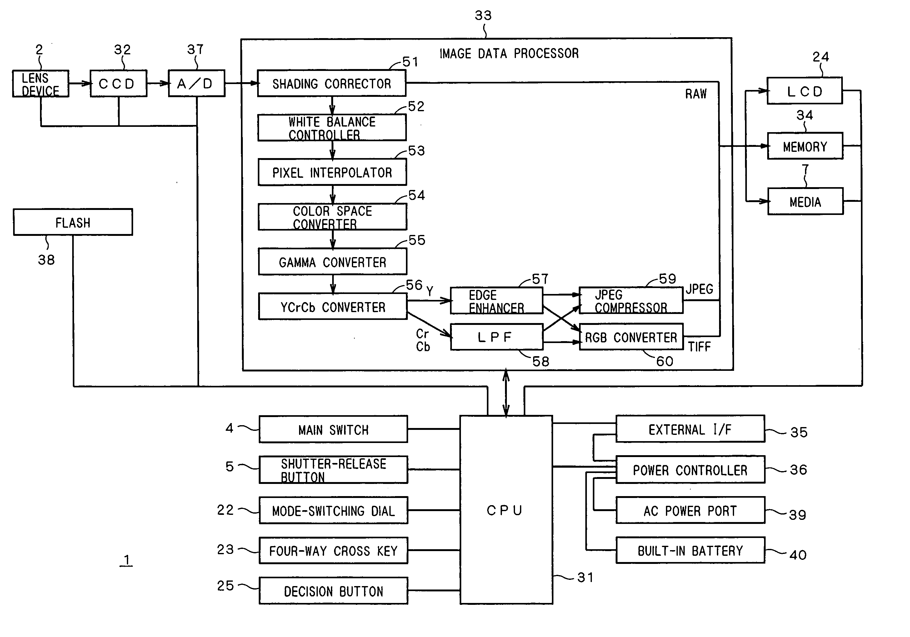
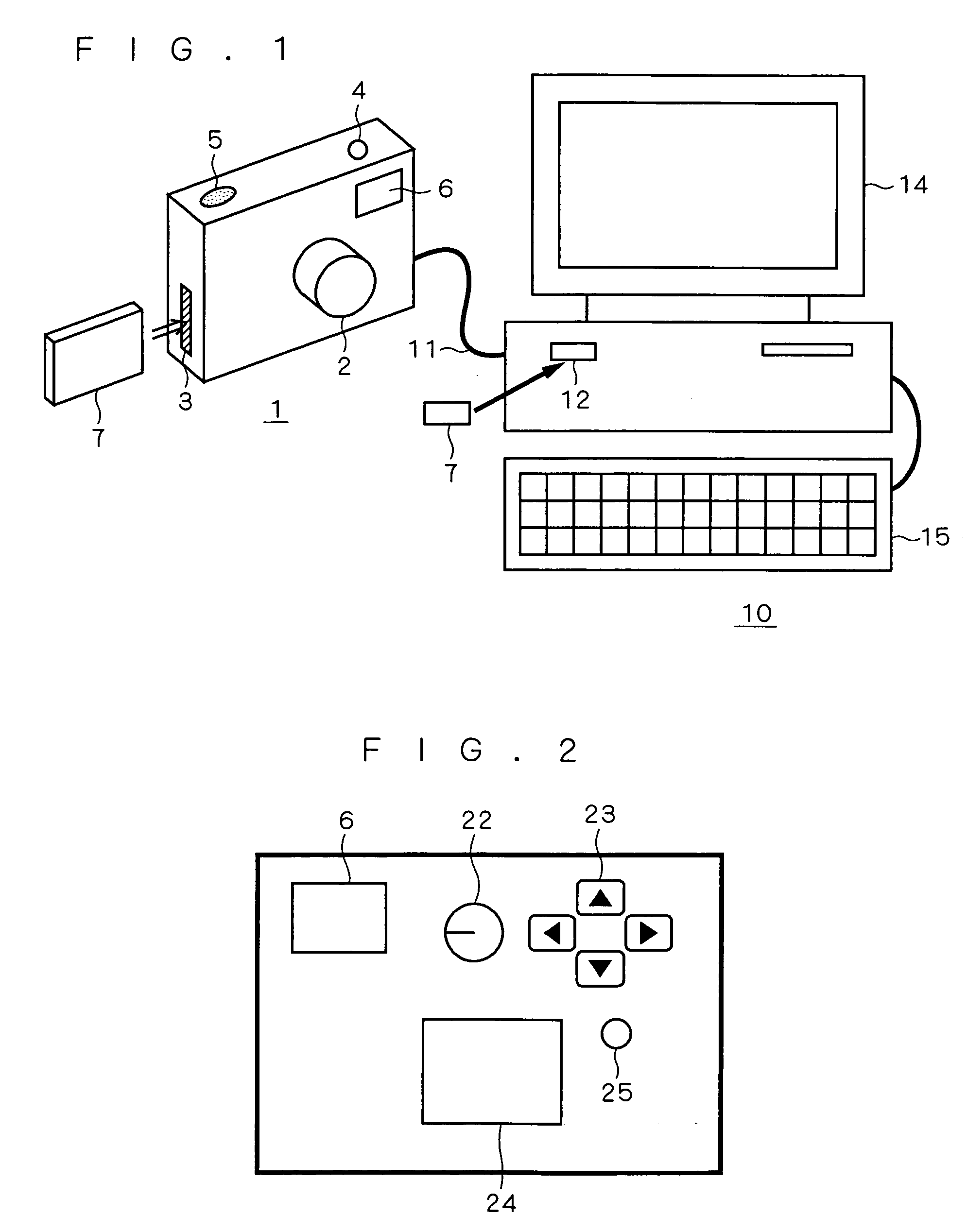
[0034]FIG. 1 shows a configuration of an image processing system according to a first preferred embodiment of the present invention. As shown in FIG. 1, a digital camera 1 serving as an image capturing apparatus and a PC (personal computer) 10 serving as an electronic processing terminal are connected to each other with a cable 11 for making communications under USB or the like.
[0035] The digital camera 1 has a lens device 2 and a viewfinder 6 on its front face; a main switch 4 and a shutter-release button 5 on its top face; and a media insertion slot 3 removably accepting a media 7 serving as a memory (recording medium) including a memory card and the like, on its side face.
[0036] The PC 10 has a monitor 14 for displaying information in the form of an image to a user and a keyboard 15 for a user to input information. The PC 10 further has a media insertion slot 12 removably accepting the media 7 on the front face of its body.
[0037]FIG. 2 is a rear view of the digi...
second preferred embodiment
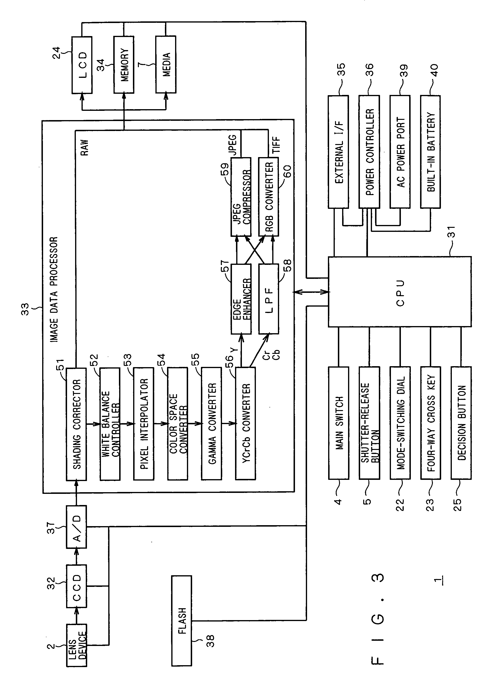
[0102] In the first preferred embodiment, only sections of the digital camera 1 related to computing and communications (transmission of image data) are used in the operation shown in the flow chart of FIG. 9. Therefore, in the operation, power supply to sections of the digital camera 1 not related to computing and communications may be stopped.
[0103]FIG. 10 is a flow chart of an operation of the digital camera 1 according to a second preferred embodiment of the present invention. The flow chart shown in FIG. 10 differs from that of FIG. 9 in that step S31-1 prior to step S31 and step S38-1 subsequent to step 38 are added.
[0104] In step S31-1, the digital camera 1 uses the power controller 36 to stop power supply to the sections not related to computing and communications as well as to switch the power source to an optimum one. In step S38-1, the digital camera 1 uses the power controller 36 to restart power supply to the sections to which power supply has been stopped as well as ...
third preferred embodiment
[0111] In the operation shown in the flow chart of FIG. 8 according to the first preferred embodiment, when it is judged in step S21 that the digital camera 1 is connected, and it is judged in step S22 that the digital camera 1 is not busy, then, the digital camera 1 performs conversion processing in step S24 after the PC 10 transmits image data and computing parameters to the digital camera 1 in step S23. In some cases, however, the PC 10 may perform conversion processing faster than the digital camera 1 depending on details of the conversion processing.
[0112]FIG. 12 is a flow chart of the operation of the digital camera 1 according to a third preferred embodiment. The flow chart of FIG. 12 differs from that of FIG. 8 in that step S21-1 prior to step S21 is added.
[0113] In step S21-1, the PC 10 judges which of the digital camera 1 and PC 10 performs conversion processing faster. This judgment is made based on the computing power of the digital camera 1, the computing power of the...
PUM
 Abstract
Description
Claims
Application Information
 - R&D
- Intellectual Property
- Life Sciences
- Materials
- Tech Scout
- Unparalleled Data Quality
- Higher Quality Content
- 60% Fewer Hallucinations
Browse by: Latest US Patents, China's latest patents, Technical Efficacy Thesaurus, Application Domain, Technology Topic, Popular Technical Reports.
© 2025 PatSnap. All rights reserved.Legal|Privacy policy|Modern Slavery Act Transparency Statement|Sitemap|About US| Contact US: help@patsnap.com


